Components
COMPONENTS
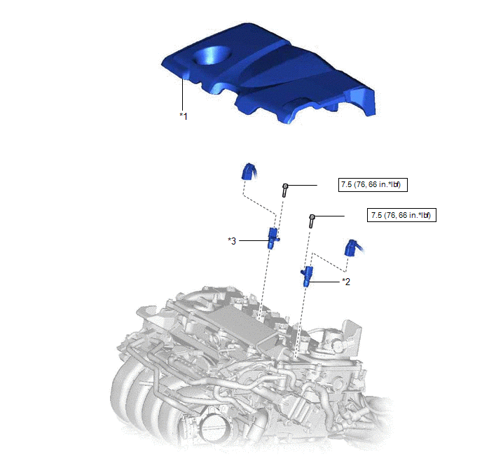
ILLUSTRATION
|
*1 | NO. 1 ENGINE COVER SUB-ASSEMBLY |
*2 | CAMSHAFT POSITION SENSOR (for Intake Side) |
|
*3 | CAMSHAFT POSITION SENSOR (for Exhaust Side) |
- | - |
 |
N*m (kgf*cm, ft.*lbf): Specified torque |
ŌŚÅ | Non-reusable part |
|
Ōśģ | Precoated part |
- | - |
Installation
INSTALLATION
CAUTION / NOTICE / HINT
NOTICE:
This procedure includes the installation of small-head bolts. Refer to Small-Head Bolts of Basic Repair Hint to identify the small-head bolts.
Click here

PROCEDURE
1. INSTALL CAMSHAFT POSITION SENSOR (for Exhaust Side)
(a) Apply a light coat of engine oil to the O-ring of the camshaft position sensor.
NOTICE:
If reusing the camshaft position sensor, be sure to inspect the O-ring.
(b) Using an 8 mm socket wrench, install the camshaft position sensor to the cylinder head cover sub-assembly with a new bolt.
Torque:
7.5 N┬Ęm {76 kgf┬Ęcm, 66 in┬Ęlbf}
NOTICE:
(c) Connect the camshaft position sensor connector.
2. INSTALL CAMSHAFT POSITION SENSOR (for Intake Side)
(a) Apply a light coat of engine oil to the O-ring of the camshaft position sensor.
NOTICE:
If reusing the camshaft position sensor, be sure to inspect the O-ring.
(b) Using an 8 mm socket wrench, install the camshaft position sensor to the cylinder head cover sub-assembly with a new bolt.
Torque:
7.5 N┬Ęm {76 kgf┬Ęcm, 66 in┬Ęlbf}
NOTICE:
(c) Connect the camshaft position sensor connector.
3. INSPECT FOR ENGINE OIL LEAK
Click here
4. INSTALL NO. 1 ENGINE COVER SUB-ASSEMBLY
Click here
Removal
REMOVAL
CAUTION / NOTICE / HINT
NOTICE:
This procedure includes the removal of small-head bolts. Refer to Small-Head Bolts of Basic Repair Hint to identify the small-head bolts.
Click here

PROCEDURE
1. REMOVE NO. 1 ENGINE COVER SUB-ASSEMBLY
Click here
2. REMOVE CAMSHAFT POSITION SENSOR (for Intake Side)
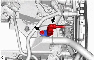
| (a) Disconnect the camshaft position sensor connector. |
|
(b) Using an 8 mm socket wrench, remove the bolt and camshaft position sensor from the cylinder head cover sub-assembly.
NOTICE:
If the camshaft position sensor has been struck or dropped, replace it.
3. REMOVE CAMSHAFT POSITION SENSOR (for Exhaust Side)
(a) Disconnect the camshaft position sensor connector.
| (b) Using an 8 mm socket wrench, remove the bolt and camshaft position sensor from the cylinder head cover sub-assembly. NOTICE: If the camshaft position sensor has been struck or dropped, replace it. |
|
Toyota Avalon (XX50) 2019-2022 Service & Repair Manual > Hybrid Control System: Lost Communication with Drive Motor Control Module "A" from Hybrid/EV Control Module Missing Message (P312387)
DESCRIPTION For a description of the inverter. Click here The MG ECU, which is built into in the inverter with converter assembly, controls motor (MG2) based on commands from the hybrid vehicle control ECU. The MG ECU monitors communication data and detects malfunctions. The hybrid vehicle control E ...