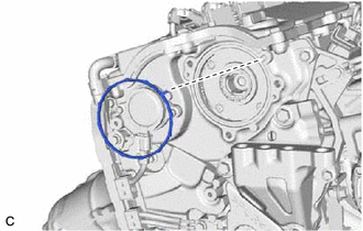
Components
COMPONENTS
ILLUSTRATION
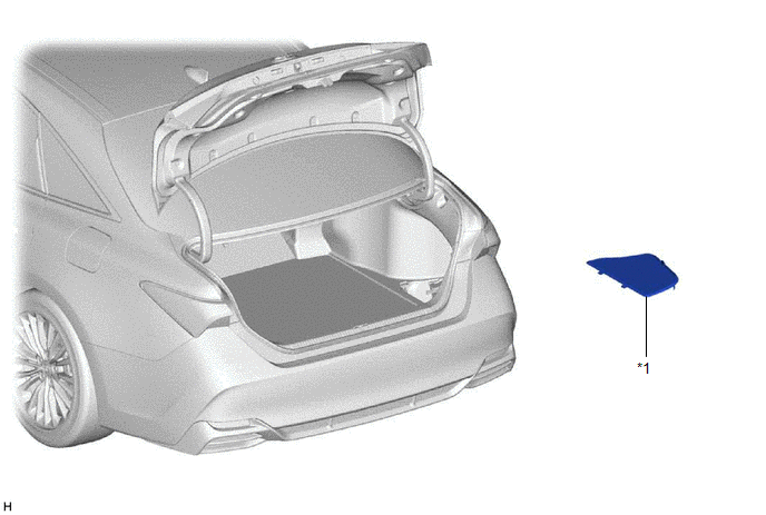
|
*1 | LUGGAGE TRIM SERVICE HOLE COVER |
- | - |
ILLUSTRATION
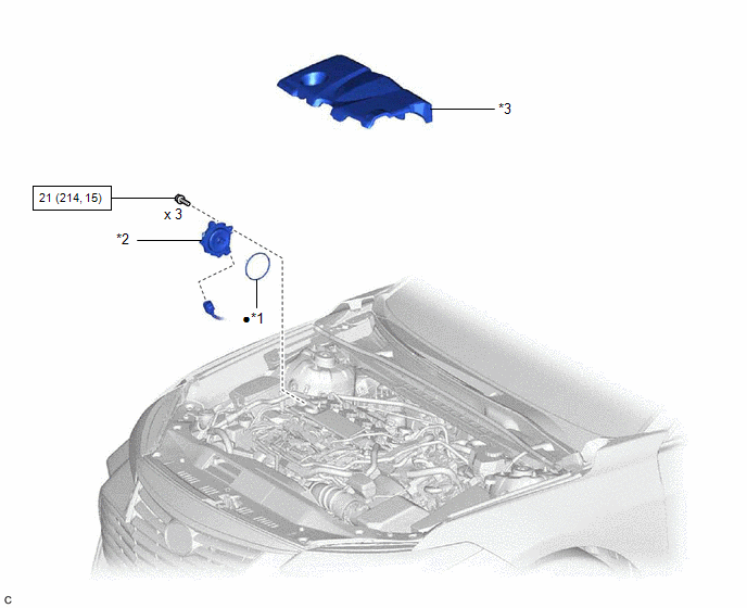
|
*1 | CAM TIMING CONTROL MOTOR O-RING |
*2 | CAM TIMING CONTROL MOTOR WITH EDU ASSEMBLY |
|
*3 | NO. 1 ENGINE COVER SUB-ASSEMBLY |
- | - |
 |
N*m (kgf*cm, ft.*lbf): Specified torque |
â—Ź | Non-reusable part |
Inspection
INSPECTION
CAUTION / NOTICE / HINT
NOTICE:
- Make sure the contact surface of the cam timing control motor with EDU
assembly (the surface that contacts the No. 2 timing chain cover
assembly) is free of foreign matter.
- If the cam timing control motor with EDU assembly has been struck or dropped, replace it.
- Do not disassemble the cam timing control motor with EDU assembly. If disassembled, replace it.
PROCEDURE
1. INSPECT CAM TIMING CONTROL MOTOR WITH EDU ASSEMBLY
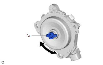
| (a) Rotate the joint of the cam timing control motor with EDU assembly by hand and check that it rotates smoothly.
Standard Condition: The joint rotates smoothly. HINT:
Due
to the magnetic force of the cam timing control motor with EDU assembly
the joint may feel as if it is sticking when turning it. If the result is not as specified, replace the cam timing control motor with EDU assembly. |
|
2. INSPECT CAMSHAFT TIMING GEAR ASSEMBLY
NOTICE:
- If the camshaft timing gear assembly has been struck or dropped, replace it.
- Do not disassemble the camshaft timing gear assembly. If disassembled, replace it.
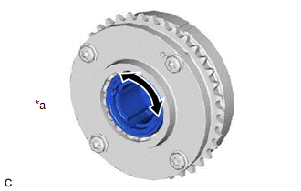
| (a) Rotate the camshaft timing gear assembly eccentric shaft by hand.
Standard Condition: The shaft rotates smoothly.
HINT:
- The eccentric shaft may feel difficult to rotate due to the spring inside the camshaft timing gear assembly.
- If the result is not as specified, replace the camshaft timing gear assembly.
| |
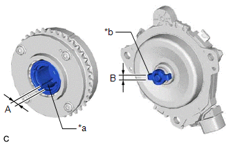
| (b) Inspect the joint clearance. (1) Using a vernier caliper, measure the width (A) of the cutout of the camshaft timing gear assembly eccentric shaft.
Standard Width: 5.98 to 6.05 mm (0.235 to 0.238 in.) (2) Using a vernier caliper, measure the width (B) of the joint of the cam timing control motor with EDU assembly.
Standard Width: 5.90 to 5.95 mm (0.232 to 0.234 in.) (3)
Calculate the clearance by subtracting the width (B) of the joint of
the cam timing control motor with EDU assembly from the width (A) of the
cutout of the camshaft timing gear assembly eccentric shaft. Standard Clearance:
0.03 to 0.15 mm (0.00118 to 0.00591 in.) Maximum Clearance:
0.7 mm (0.0276 in.) HINT: If
the clearance is more than the maximum, replace the camshaft timing
gear assembly or cam timing control motor with EDU assembly. | |
Installation
INSTALLATION
CAUTION / NOTICE / HINT
NOTICE:
This
procedure includes the installation of small-head bolts. Refer to
Small-Head Bolts of Basic Repair Hint to identify the small-head bolts.
Click here

PROCEDURE
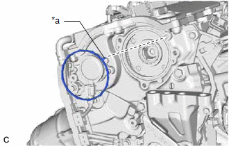
1. INSTALL CAM TIMING CONTROL MOTOR O-RING
| (a)
Install a new cam timing control motor O-ring to the No. 2 timing chain
cover assembly with the protrusion of the cam timing control motor
O-ring oriented as shown in the illustration. | |
2. INSTALL CAM TIMING CONTROL MOTOR WITH EDU ASSEMBLY
HINT:
Perform "Inspection After Repair" after removing and installing, or replacing the cam timing control motor with EDU assembly.
Click here 
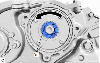
| (a)
Turn the cutout of the camshaft timing gear assembly eccentric shaft
counterclockwise by hand, and set it to the maximum retard angle
position.
HINT:
- If a camshaft lobe is opening a valve, the eccentric shaft will be difficult to turn.
- When the cutout of the camshaft timing gear assembly eccentric shaft
cannot be turned any farther, it is set to the maximum retard angle.
| |
| (b) Install the cam timing control motor with EDU assembly to the No. 2 timing chain cover assembly.
NOTICE:
- When installing, align the joints of the cam timing control motor with
EDU assembly with the cutouts of the camshaft timing gear assembly
eccentric shaft.
- Align the pin holes of the cam timing control motor with EDU assembly
with the knock pins of the No. 2 timing chain cover assembly when
installing the cam timing control motor with EDU assembly.
- Make sure the contact surface of the cam timing control motor with EDU
assembly (the surface that contacts the No. 2 timing chain cover
assembly) is free of foreign matter.
- When installing the cam timing control motor with EDU assembly, do not use excessive force.
- If the cam timing control motor with EDU assembly has been struck or dropped, replace it.
- Do not disassemble the cam timing control motor with EDU assembly. If disassembled, replace it.
|
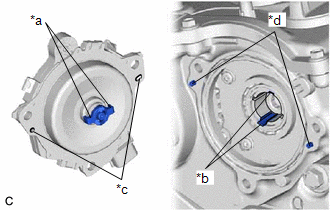 |
|
*a | Joint | |
*b | Cutout | |
*c | Pin Hole | |
*d | Knock Pin | | |
(c) Install the 3 bolts.
Torque:
21 N·m {214 kgf·cm, 15 ft·lbf}
(d) Connect the cam timing control motor with EDU assembly connector.
3. CONNECT CABLE TO NEGATIVE AUXILIARY BATTERY TERMINAL
Click here 
4. INSTALL LUGGAGE TRIM SERVICE HOLE COVER
Click here 
5. INSPECT FOR ENGINE OIL LEAK
Click here 
6. INSTALL NO. 1 ENGINE COVER SUB-ASSEMBLY
Click here 
7. PERFORM INITIALIZATION
(a)
Perform "Inspection After Repair" after removing and installing, or
replacing the cam timing control motor with EDU assembly.
Click here

On-vehicle Inspection
ON-VEHICLE INSPECTION
PROCEDURE
1. INSPECT CAM TIMING CONTROL MOTOR WITH EDU ASSEMBLY
(a) Check Rotation Direction Signal:
(1) Connect the Techstream to the DLC3.
(2) Turn the power switch on (IG).
(3) Turn the Techstream on.
(4) Enter the following menus: Powertrain / Engine / Data List / VVT-iE Motor Direction Bank1.
Powertrain > Engine > Data List
|
Tester Display |
| VVT-iE Motor Direction Bank 1 |
(5) According to the display on the Techstream, read the Data List.
Specified Condition:
|
Techstream Display | Condition |
Specified Condition |
|
VVT-iE Motor Direction Bank1 |
Power switch off → Power switch on (IG) |
Backward |
HINT:
If the result is not as specified, inspect the cam timing control motor with EDU assembly and wire harness.
(b) Check VVT Change Angle:
(1) Connect the Techstream to the DLC3.
(2) Turn the power switch on (IG).
(3) Turn the Techstream on.
(4) Put the engine in Inspection Mode (Maintenance Mode).
Powertrain > Hybrid Control > Utility
|
Tester Display |
| Inspection Mode |
(5) Start the engine and warm it up until the engine coolant temperature reaches 75°C (167°F) or higher.
(6)
Enter the following menus: Powertrain / Engine / Active Test / Control
the VVT-iE Opening Angle Bank 1 / Data List / Intake VVT Change Angle
Bank 1 and Intake VVT Target Angle Bank 1.
Powertrain > Engine > Active Test
|
Active Test Display |
|
Control the VVT-iE Opening Angle Bank 1 |
|
Data List Display |
|
Intake VVT Change Angle Bank 1 |
|
Intake VVT Target Angle Bank 1 |
(7) Read the Data List while performing the Active Test with the engine idling.
Specified Condition:
|
Active Test Movement Order |
Difference between "Intake VVT Change Angle Bank 1" and "Intake VVT Target Angle Bank 1" |
|
0 deg → 10 deg → 20 deg → 40 deg → 0 deg → 10 deg → END |
Within 4 DegFR |
HINT:
If the result is not as specified, inspect the cam timing control motor with EDU assembly and camshaft timing gear assembly.
Removal
REMOVAL
CAUTION / NOTICE / HINT
The
necessary procedures (adjustment, calibration, initialization, or
registration) that must be performed after parts are removed and
installed, or replaced during cam timing control motor with EDU assembly
removal/installation are shown below.
Necessary Procedures After Parts Removed/Installed/Replaced |
Replaced Part or Performed Procedure |
Necessary Procedure | Effect/Inoperative Function when Necessary Procedure not Performed |
Link |
|
*: When performing learning using the Techstream.
Click here  |
|
Auxiliary battery terminal is disconnected/reconnected |
Perform steering sensor zero point calibration |
Lane Departure Alert System (w/ Steering Control) |
 |
|
Pre-collision System |
|
Intelligent Clearance Sonar System* |
|
Lighting System (for HV Model with Cornering Light) |
|
Memorize steering angle neutral point |
Parking Assist Monitor System |
 |
|
Panoramic View Monitor System |
 |
- Replacement of cam timing control motor with EDU assembly
- Removal and installation of a cam timing control motor with EDU assembly
| Inspection after repair |
- Poor idle, etc.
- Engine start function, etc.
|
 |
NOTICE:
- After turning the power switch off, waiting time may be required before
disconnecting the cable from the negative (-) auxiliary battery
terminal. Therefore, make sure to read the disconnecting the cable from
the negative (-) auxiliary battery terminal notices before proceeding
with work.
Click here 
- This procedure includes the removal of small-head bolts. Refer to
Small-Head Bolts of Basic Repair Hint to identify the small-head bolts.
Click here 
PROCEDURE
1. REMOVE LUGGAGE TRIM SERVICE HOLE COVER
Click here 
2. DISCONNECT CABLE FROM NEGATIVE AUXILIARY BATTERY TERMINAL
Click here 
3. REMOVE NO. 1 ENGINE COVER SUB-ASSEMBLY
Click here 
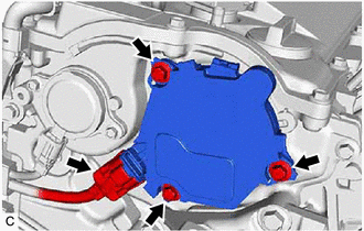
4. REMOVE CAM TIMING CONTROL MOTOR WITH EDU ASSEMBLY
| (a) Disconnect the cam timing control motor with EDU assembly connector. |
|
(b) Remove the 3 bolts and cam timing control motor with EDU assembly from the No. 2 timing chain cover assembly.
NOTICE:
If the cam timing control motor with EDU assembly has been struck or dropped, replace it.
5. REMOVE CAM TIMING CONTROL MOTOR O-RING
| (a) Remove the cam timing control motor O-ring from the No. 2 timing chain cover assembly. |
|


