Installation
INSTALLATION
PROCEDURE
1. INSTALL MASS AIR FLOW METER SUB-ASSEMBLY
HINT:
Perform "Inspection After Repair" after replacing the mass air flow meter sub-assembly.
Click here 
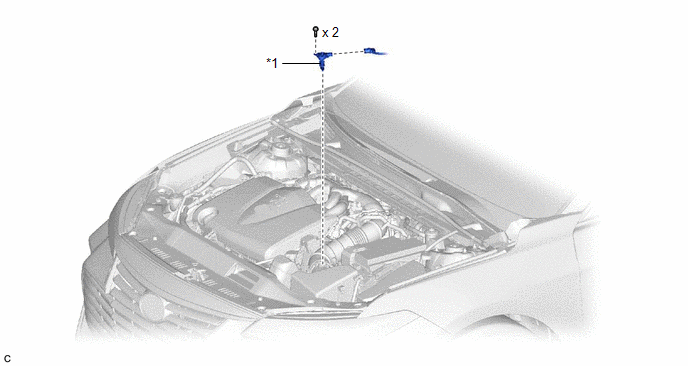
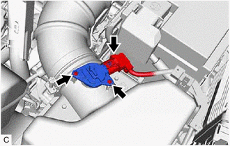
(a) Install the mass air flow meter sub-assembly to the air cleaner cap sub-assembly with the 2 screws.
NOTICE:
- If the mass air flow meter sub-assembly has been struck or dropped, replace it.
- If reusing the mass air flow meter sub-assembly, be sure to inspect the O-ring.
- Make sure that the O-ring is not cracked or moved out of place when installing the mass air flow meter sub-assembly.
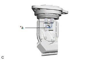
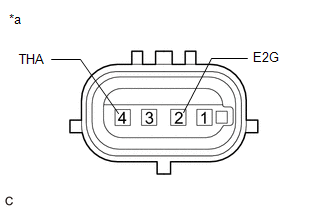
(b) Connect the mass air flow meter sub-assembly connector.
2. PERFORM INITIALIZATION
(a) Perform "Inspection After Repair" after replacing the mass air flow meter sub-assembly.
Click here
On-vehicle Inspection
ON-VEHICLE INSPECTION
PROCEDURE
1. INSPECT MASS AIR FLOW METER SUB-ASSEMBLY
HINT:
Perform "Inspection After Repair" after replacing the mass air flow meter sub-assembly.
Click here 
(a) Read the value of Data List item "Mass Air Flow Sensor" using the Techstream.
NOTICE:
Perform
the inspection of the mass air flow meter sub-assembly while it is
installed to the air cleaner cap sub-assembly (installed to the
vehicle).
(1) Connect the Techstream to the DLC3.
(2) Start the engine.
(3) Turn the Techstream on.
(4) Enter the following menus: Powertrain / Engine / Data List / Mass Air Flow Sensor.
Powertrain > Engine > Data List
|
Tester Display |
| Mass Air Flow Sensor |
(5) According to the display on the Techstream, read the Data List when the engine is running.
Standard Condition:
|
Techstream Display | Condition |
Specified Condition |
|
Mass Air Flow Sensor |
Idling (engine warmed up) |
2.6 to 3.7 gm/sec |
|
2000 rpm (without load) |
5.4 to 9.6 gm/sec |
|
3000 rpm (without load) |
10.6 to 15.8 gm/sec |
If the result is not as specified, replace the mass air flow meter sub-assembly.
If the result is within the specified range, remove and inspect the mass air flow meter sub-assembly.
Click here
2. PERFORM INITIALIZATION
(a) Perform "Inspection After Repair" after replacing the mass air flow meter sub-assembly.
Click here
Removal
REMOVAL
CAUTION / NOTICE / HINT
The
necessary procedures (adjustment, calibration, initialization or
registration) that must be performed after parts are removed and
installed, or replaced during mass air flow meter sub-assembly
removal/installation are shown below.
Necessary Procedures After Parts Removed/Installed/Replaced |
Replaced Part or Performed Procedure |
Necessary Procedure | Effect/Inoperative Function when Necessary Procedure not Performed |
Link |
| Replacement of mass air flow meter sub-assembly |
Inspection after repair |
- Poor idle, etc.
- Engine start function, etc.
|
 |
PROCEDURE
1. REMOVE MASS AIR FLOW METER SUB-ASSEMBLY
| (a) Disconnect the mass air flow meter sub-assembly connector. |
|
(b) Remove the 2 screws and mass air flow meter sub-assembly from the air cleaner cap sub-assembly.
NOTICE:
If the mass air flow meter sub-assembly has been struck or dropped, replace it.