On-vehicle Inspection
ON-VEHICLE INSPECTION
PROCEDURE
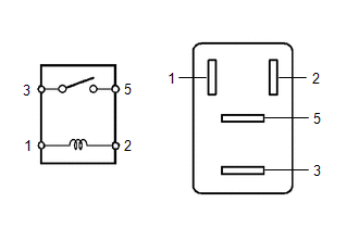
1. INSPECT NO. 1 ELECTRONIC FUEL INJECTION MAIN RELAY (EFI-MAIN NO. 1)
| (a) Measure the resistance according to the value(s) in the table below. Standard Resistance:
If the result is not as specified, replace the No. 1 electronic fuel injection main relay (EFI-MAIN NO. 1). |
|
2. INSPECT NO. 2 ELECTRONIC FUEL INJECTION MAIN RELAY (EFI-MAIN NO. 2)
| (a) Measure the resistance according to the value(s) in the table below. Standard Resistance:
If the result is not as specified, replace the No. 2 electronic fuel injection main relay (EFI-MAIN NO. 2). |
|
3. INSPECT NO. 3 ELECTRONIC FUEL INJECTION MAIN RELAY (EFI-MAIN NO. 3)
| (a) Measure the resistance according to the value(s) in the table below. Standard Resistance:
If the result is not as specified, replace the No. 3 electronic fuel injection main relay (EFI-MAIN NO. 3). |
|
4. INSPECT INJECTOR RELAY (D INJ)
| (a) Measure the resistance according to the value(s) in the table below. Standard Resistance:
If the result is not as specified, replace the injector relay (D INJ). |
|
5. INSPECT NO. 2 IGNITION RELAY (IG2 NO. 1)
| (a) Measure the resistance according to the value(s) in the table below. Standard Resistance:
If the result is not as specified, replace the No. 2 ignition relay (IG2 NO. 1). |
|
Toyota Avalon (XX50) 2019-2022 Service & Repair Manual > Meter / Gauge System(for Gasoline Model): Lost Communication with EMV Missing Message (B132187). Fuel Sender Circuit Open (B150013). Turn Signal Light Circuit Current Below Threshold (B150718)
Lost Communication with EMV Missing Message (B132187) DESCRIPTION The combination meter assembly and radio and display receiver assembly communicate via local bus communication. This allows audio and visual system information to be displayed on the multi-information display. This DTC is stored when ...