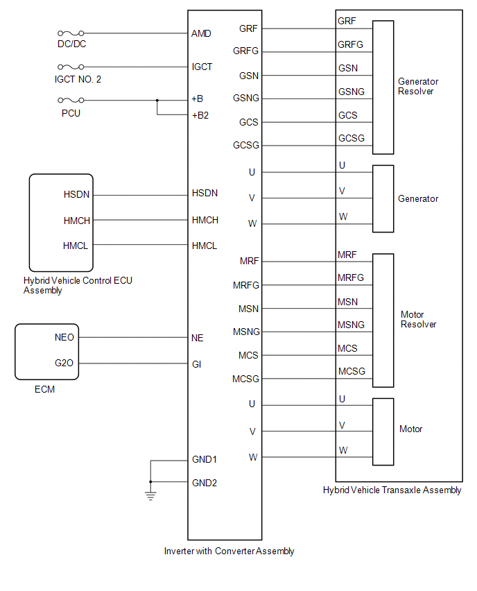
Precaution
PRECAUTION
PRECAUTIONS FOR INSPECTING HYBRID CONTROL SYSTEM
(a)
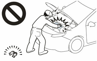
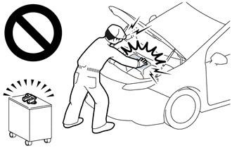
Before the following operations are conducted, take precautions to
prevent electric shock by turning the power switch off, wearing
insulated gloves, and removing the service plug grip from HV battery.
- Inspecting the high-voltage system
- Disconnecting the low voltage connector of the inverter with converter assembly
- Disconnecting the low voltage connector of the HV battery
NOTICE:
- After turning the power switch off, waiting time may be required before
disconnecting the cable from the negative (-) auxiliary battery
terminal. Therefore, make sure to read the disconnecting the cable from
the negative (-) auxiliary battery terminal notices before proceeding
with work.
Click here 
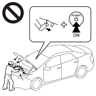
- After removing the service plug grip, turning the power switch on
(READY) may cause a malfunction. Do not turn the power switch on (READY)
unless instructed by the repair manual.
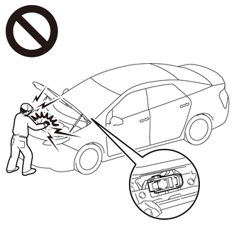
(b) To prevent electric shock, make
sure to remove the service plug grip to cut off the high voltage circuit
before servicing the vehicle.
(c)
After removing the service plug grip, put it in your pocket to prevent
other technicians from accidentally reconnecting it while you are
working on the high-voltage system.
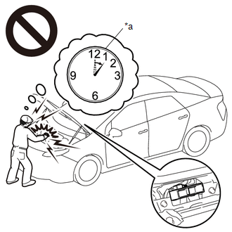
(d)
After removing the service plug grip, wait for at least 10 minutes
before touching any of the high-voltage connectors or terminals.
HINT:
Waiting for at least 10 minutes is required to discharge the high-voltage capacitor inside the inverter with converter assembly.
|
*a | Without waiting for 10 minutes |
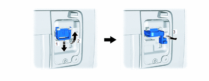
(e) Check the voltage at the terminals in the inspection point of the inverter with converter assembly.
CAUTION:
Be sure to wear insulated gloves.
(1) Remove the connector cover assembly from the inverter with converter assembly.
Click here
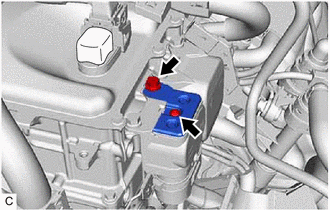
NOTICE:
- Do not touch the connector cover assembly waterproof seal.
- Do not allow any foreign matter or water to enter the inverter with converter assembly.
(2) Measure the voltage according to the value(s) in the table below.
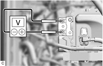
Standard Voltage:
|
Tester Connection | Condition |
Specified Condition |
|
Inspection point | At least 10 minutes after removing the service plug grip |
0 V |
HINT:
Make sure to set the tester to DC750 V or more when measuring the voltage.
(3) Reinstall the connector cover assembly.
(f) When turning the power switch on (IG) during an inspection, do not press the power switch while depressing the brake pedal.
CAUTION:
Pressing
the power switch with the brake pedal depressed causes the system to
enter the READY-on state. This is very dangerous because high voltage
may be applied to the inspection area.
(g)
Turn the power switch off, disconnect the cable from the negative (-)
terminal of the auxiliary battery and put on insulated gloves before
touching any of the orange-colored wire harnesses and connectors of the
high-voltage system.
NOTICE:
After
turning the power switch off, waiting time may be required before
disconnecting the cable from the negative (-) auxiliary battery
terminal. Therefore, make sure to read the disconnecting the cable from
the negative (-) auxiliary battery terminal notices before proceeding
with work.
Click here
(h) Turn the power switch off before performing any resistance checks.
(i) Turn the power switch off before disconnecting or reconnecting any connectors.
(j)
When performing work involving high-voltage wires, use either a tool
wrapped with vinyl insulating tape or an insulated tool.
(k)
When high-voltage connectors are removed, wrap the connectors with
insulation tape to prevent them from contacting foreign matter.
NOTICE FOR HYBRID CONTROL SYSTEM ACTIVATION
(a)
When the warning light is illuminated, or the auxiliary battery has
been disconnected and reconnected, attempting to turn the power switch
on (READY) may not start the system (the system may not enter the
READY-on state) on the first attempt. If so, turn the power switch off
and reattempt to start the hybrid system.
NOTICE:
After
turning the power switch off, waiting time may be required before
disconnecting the cable from the negative (-) auxiliary battery
terminal. Therefore, make sure to read the disconnecting the cable from
the negative (-) auxiliary battery terminal notices before proceeding
with work.
Click here
PRECAUTIONS FOR DISCONNECTING AMD TERMINAL
HINT:
The
AMD terminal is connected to the positive terminal of the auxiliary
battery. To prevent damage when the AMD terminal is being disconnected,
use the following procedure.
(a) Be sure to
disconnect the cable from the negative (-) auxiliary battery terminal
before disconnecting the AMD terminal from the No. 1 engine room relay
block and junction block assembly.
NOTICE:
After
turning the power switch off, waiting time may be required before
disconnecting the cable from the negative (-) auxiliary battery
terminal. Therefore, make sure to read the disconnecting the cable from
the negative (-) auxiliary battery terminal notices before proceeding
with work.
Click here
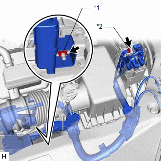
|
*1 | AMD Terminal (Inverter with Converter Assembly Side) |
|
*2 | AMD Terminal (No. 1 Engine Room Relay Block and No. 1 Junction Block Assembly Side) |
(b) After disconnecting the AMD terminal, wrap it with vinyl insulating tape.
(c)
Be sure to reconnect the AMD terminal to the No. 1 engine room relay
block and junction block assembly before reconnecting the cable to the
negative (-) terminal of the auxiliary battery.
NOTICE:
A
short circuit to ground may occur if the AMD terminal is disconnected
before the cable is disconnected from the negative (-) auxiliary battery
terminal. If a short circuit to ground occurs, a fusible link or fuse
may break.
DISPOSING OF A HV BATTERY
(a)
When disposing of an HV battery, make sure to return it through an
authorized collection agent who is capable of handling it safely. If the
HV battery is returned via the manufacturer specified route, it will be
returned properly and in a safe manner by an authorized collection
agent.
CAUTION:
- After removing the HV battery, keep it away from water. Exposure to
water may cause the HV battery to produce heat, resulting in a fire.
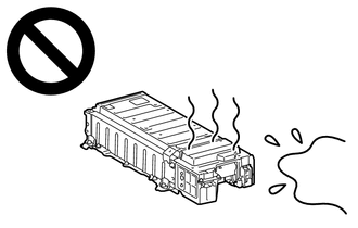
- Accidents such as electric shock may result if the HV battery is disposed of improperly or abandoned.
Therefore, make sure to return HV battery through an authorized collection agent.
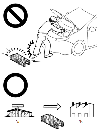
|
*a |
Dealer |
|
*b |
Battery Collection Agent |
- To reduce the risk of fire, HV battery must not be stored in an area where they will be exposed to fire or high temperatures.
- If the temperature of the HV battery is high, leave the vehicle until the temperature drops.
- Make sure to insulate the high-voltage connectors and terminals of the HV battery with insulating tape after removing it.
If the HV battery stored without insulating the connectors and terminals, electric shock or fire may result.
PRECAUTIONS WHEN REPLACING HYBRID VEHICLE CONTROL ECU
NOTICE:
PRECAUTIONS WHEN REPLACING HYBRID VEHICLE CONTROL ECU
Click here
|
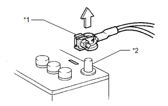
*1 | Cable |
|
*2 | Negative (-) Battery Terminal |
DISCONNECTING AND RECONNECTING NEGATIVE AUXILIARY BATTERY CABLE
(a)
Before performing work on electronic components, disconnect the cable
from the negative (-) auxiliary battery terminal to prevent damage to
the electrical system or electrical components.
(b)
Before disconnecting and reconnecting the auxiliary battery cable, turn
the power switch off and the headlight switch off. Then loosen the
terminal nut completely. Do not damage the cable or terminal.
(c)
When the auxiliary battery cable is disconnected, the clock and radio
settings and stored DTCs are cleared. Therefore, before disconnecting
the auxiliary battery cable, make a note of them.
NOTICE:
- After turning the power switch off, waiting time may be required before
disconnecting the cable from the negative (-) auxiliary battery
terminal. Therefore, make sure to read the disconnecting the cable from
the negative (-) auxiliary battery terminal notices before proceeding
with work.
Click here
- When the cable is disconnected from the negative (-) auxiliary battery
terminal, initialize the following systems after the cable is
reconnected.
| System Name |
See Procedure |
| Lane Departure Alert System (w/ Steering Control) |
|
|
Pre-collision system |
| Intelligent Clearance Sonar System |
|
Parking assist monitor system |
| Panoramic view monitor system |
|
Lighting System (for HV Model with Cornering Light) |