Installation
INSTALLATION
PROCEDURE
1. INSTALL MASS AIR FLOW METER SUB-ASSEMBLY
HINT:
Perform "Inspection After Repair" after replacing the mass air flow meter sub-assembly.
Click here 
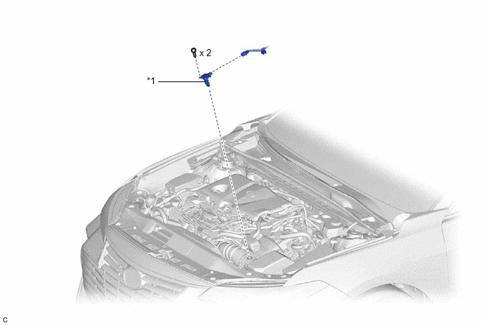
(a) Install the mass air flow meter sub-assembly to the air cleaner cap sub-assembly with the 2 screws.
NOTICE:
- If the mass air flow meter sub-assembly has been struck or dropped, replace it.
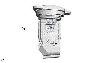
- If reusing the mass air flow meter sub-assembly, be sure to inspect the O-ring.
- Make sure that the O-ring is not cracked or moved out of place when installing the mass air flow meter sub-assembly.
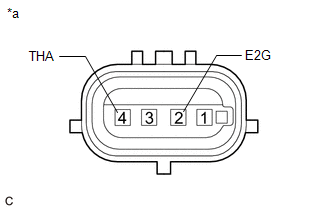
(b) Connect the mass air flow meter sub-assembly connector.
2. PERFORM INITIALIZATION
(a) Perform "Inspection After Repair" after replacing the mass air flow meter sub-assembly.
Click here 
On-vehicle Inspection
ON-VEHICLE INSPECTION
PROCEDURE
1. INSPECT MASS AIR FLOW METER SUB-ASSEMBLY
HINT:
Perform "Inspection After Repair" after replacing the mass air flow meter sub-assembly.
Click here 
(a) Read the value of Data List item "Mass Air Flow Sensor" using the Techstream.
NOTICE:
Perform
the inspection of the mass air flow meter sub-assembly while it is
installed to the air cleaner cap sub-assembly (installed to the
vehicle).
(1) Connect the Techstream to the DLC3.
(2) Turn the power switch on (IG).
(3) Turn the Techstream on.
(4) Put the engine in Inspection Mode (Maintenance Mode).
Powertrain > Hybrid Control > Utility
|
Tester Display |
| Inspection Mode |
(5) Start the engine.
(6) Enter the following menus: Powertrain / Engine / Data List / Mass Air Flow Sensor.
Powertrain > Engine > Data List
|
Tester Display |
| Mass Air Flow Sensor |
(7) According to the display on the Techstream, read the Data List when the engine is running.
Standard Condition:
|
Techstream Display | Condition |
Specified Condition |
|
Mass Air Flow Sensor |
Idling (shift lever in P, engine warmed up, inspection mode [maintenance mode] and not charge control) |
2.6 to 8.6 gm/sec |
|
2500 rpm (shift lever in P, engine warmed up and inspection mode [maintenance mode] ) |
6.2 to 18.6 gm/sec |
If the result is not as specified, replace the mass air flow meter sub-assembly.
If the result is within the specified range, remove and inspect the mass air flow meter sub-assembly.
Click here 
2. PERFORM INITIALIZATION
(a) Perform "Inspection After Repair" after replacing the mass air flow meter sub-assembly.
Click here 
Removal
REMOVAL
CAUTION / NOTICE / HINT
The
necessary procedures (adjustment, calibration, initialization, or
registration) that must be performed after parts are removed and
installed, or replaced during mass air flow meter sub-assembly
removal/installation are shown below.
Necessary Procedures After Parts Removed/Installed/Replaced |
Replaced Part or Performed Procedure |
Necessary Procedure | Effect/Inoperative Function when Necessary Procedure not Performed |
Link |
| Replacement of mass air flow meter sub-assembly |
Inspection after repair |
- Poor idle, etc.
- Engine start function, etc.
|
 |
PROCEDURE
1. REMOVE MASS AIR FLOW METER SUB-ASSEMBLY
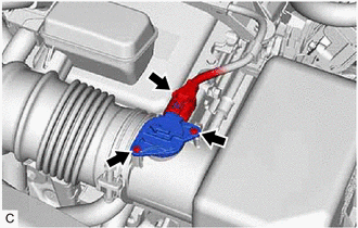
| (a) Disconnect the mass air flow meter sub-assembly connector. |
|
(b) Remove the 2 screws and mass air flow meter sub-assembly from the air cleaner cap sub-assembly.
NOTICE:
If the mass air flow meter sub-assembly has been struck or dropped, replace it.


