Components
COMPONENTS
ILLUSTRATION
|
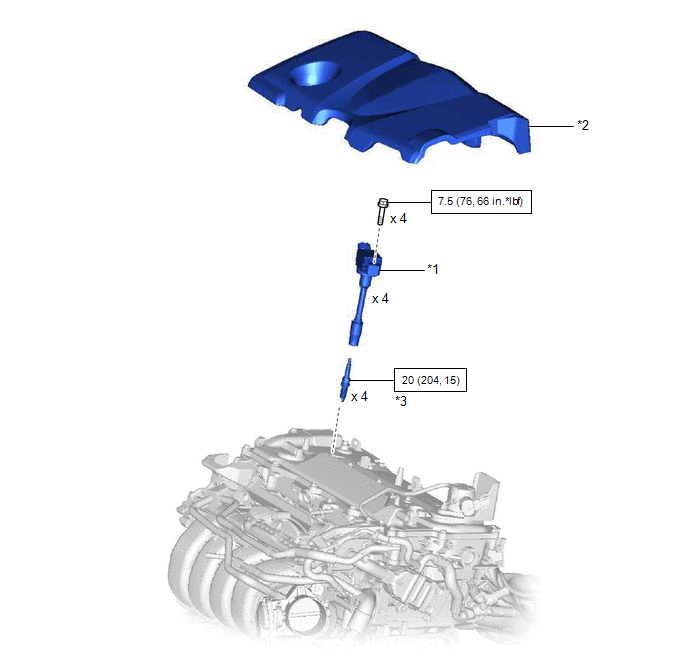
*1 | IGNITION COIL ASSEMBLY |
*2 | NO. 1 ENGINE COVER SUB-ASSEMBLY |
|
*3 | SPARK PLUG |
- | - |
 |
N*m (kgf*cm, ft.*lbf): Specified torque |
- | - |
Installation
INSTALLATION
CAUTION / NOTICE / HINT
NOTICE:
This procedure includes the installation of small-head bolts. Refer to Small-Head Bolts of Basic Repair Hint to identify the small-head bolts.
Click here

PROCEDURE
1. INSTALL SPARK PLUG
Click here
2. INSTALL IGNITION COIL ASSEMBLY
HINT:
Perform "Inspection After Repair" after replacing an ignition coil assembly.
Click here
(a) Using an 8 mm socket wrench, install the 4 ignition coil assemblies to the cylinder head cover sub-assembly with the 4 bolts.
Torque:
7.5 N·m {76 kgf·cm, 66 in·lbf}
NOTICE:
If an ignition coil assembly has been struck or dropped, replace it.
HINT:
Install the same parts to their original positions.
(b) Connect the 4 ignition coil assembly connectors.
3. INSTALL NO. 1 ENGINE COVER SUB-ASSEMBLY
Click here
4. PERFORM INITIALIZATION
(a) Perform "Inspection After Repair" after replacing an ignition coil assembly or spark plug.
Click here
Removal
REMOVAL
CAUTION / NOTICE / HINT
The necessary procedures (adjustment, calibration, initialization, or registration) that must be performed after parts are removed and installed, or replaced during ignition coil assembly or spark plug removal/installation are shown below.
Necessary Procedures After Parts Removed/Installed/Replaced|
Replaced Part or Performed Procedure |
Necessary Procedure | Effect/Inoperative Function when Necessary Procedure not Performed |
Link |
|---|---|---|---|
| Inspection after repair |
|
|
NOTICE:
This procedure includes the removal of small-head bolts. Refer to Small-Head Bolts of Basic Repair Hint to identify the small-head bolts.
Click here

PROCEDURE
1. REMOVE NO. 1 ENGINE COVER SUB-ASSEMBLY
Click here
2. REMOVE IGNITION COIL ASSEMBLY
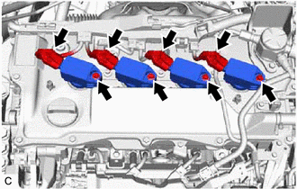
| (a) Disconnect the 4 ignition coil assembly connectors. |
|
(b) Using an 8 mm socket wrench, remove the 4 bolts and 4 ignition coil assemblies from the cylinder head cover sub-assembly.
NOTICE:
If an ignition coil assembly has been struck or dropped, replace it.
HINT:
Arrange the removed parts in the correct order.
3. REMOVE SPARK PLUG
Click here
Toyota Avalon (XX50) 2019-2022 Service & Repair Manual > Audio And Visual System(for Gasoline Model): Voice Guidance does not Function. Voice is not Recognized
Voice Guidance does not Function CAUTION / NOTICE / HINT NOTICE: Depending on the parts that are replaced during vehicle inspection or maintenance, performing initialization, registration or calibration may be needed. Refer to Precaution for Audio and Visual System. Click here When replacing the rad ...