Components
COMPONENTS
ILLUSTRATION
|
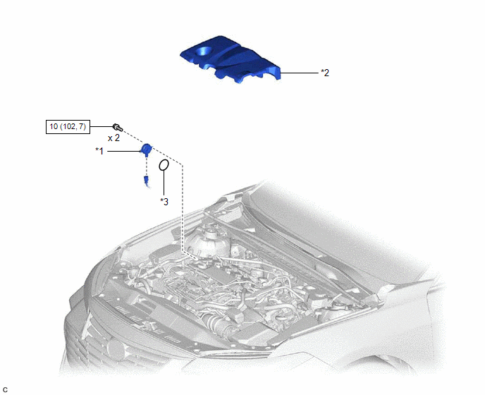
*1 | CAM TIMING OIL CONTROL SOLENOID ASSEMBLY |
*2 | NO. 1 ENGINE COVER SUB-ASSEMBLY |
|
*3 | O-RING |
- | - |
 |
N*m (kgf*cm, ft.*lbf): Specified torque |
ŌŚÅ | Non-reusable part |
|
Ōśģ | Precoated part |
- | - |
Inspection
INSPECTION
PROCEDURE
1. INSPECT CAM TIMING OIL CONTROL SOLENOID ASSEMBLY
(a) Check the resistance.
| (1) Measure the resistance according to the value(s) in the table below.
Standard Resistance: |
Tester Connection | Condition |
Specified Condition | |
1 - 2 | 0 ┬░C (32 ┬░F) |
6.3 to 7.3 ╬® | |
20 ┬░C (68 ┬░F) | 6.9 to 7.9 ╬® | |
40 ┬░C (104 ┬░F) | 7.4 to 8.6 ╬® |
If the result is not as specified, replace the cam timing oil control solenoid assembly. |
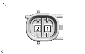 |
|
*a | Component without harness connected
(Cam Timing Oil Control Solenoid Assembly) | | |
(b) Stroke Amount Inspection
| (1)
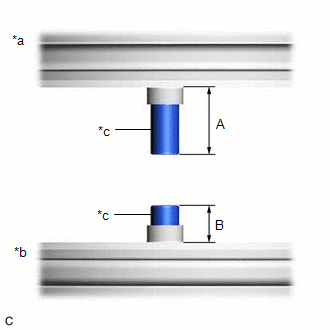
Using vernier calipers, measure length (A) and (B) with the shaft of
the cam timing oil control solenoid assembly set in the respective
positions shown in the illustration. NOTICE: Do not apply auxiliary battery voltage to the terminals of the cam timing oil control solenoid assembly.
HINT: If the shaft does not extend under its own weight, extend the shaft with your fingers. |
 |
|
*a | Shaft Side Facing Down | |
*b | Shaft Side Facing Up | |
*c | Shaft | | |
(2) Calculate the stroke amount based on the difference of length (A) and (B).
Standard:
4.3 mm (0.169 in.) or more
HINT:
Stroke amount = length (A) - length (B)
If the value is not as specified, replace the cam timing oil control solenoid assembly.
Installation
INSTALLATION
CAUTION / NOTICE / HINT
NOTICE:
This
procedure includes the installation of small-head bolts. Refer to
Small-Head Bolts of Basic Repair Hint to identify the small-head bolts.
Click here

PROCEDURE
1. INSTALL O-RING
HINT:
Perform this procedure only when replacement of the O-ring is necessary.
(a) Clean the O-ring groove of the cam timing oil control solenoid assembly.
NOTICE:
Make sure the O-ring groove is free of foreign matter.
(b) Install a new O-ring to the cam timing oil control solenoid assembly.
NOTICE:
Do not damage the O-ring when installing it.
2. INSTALL CAM TIMING OIL CONTROL SOLENOID ASSEMBLY
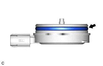
| (a) Apply a light coat of engine oil to the O-ring of the cam timing oil control solenoid assembly.
NOTICE: If reusing the cam timing oil control solenoid assembly, be sure to inspect the O-ring. |
|
(b)
Using an 8 mm socket wrench, install the cam timing oil control
solenoid assembly to the No. 2 timing chain cover assembly with 2 new
bolts.
Torque:
10 N┬Ęm {102 kgf┬Ęcm, 7 ft┬Ęlbf}
NOTICE:
- If the cam timing oil control solenoid assembly has been struck or dropped, replace it.
- Make sure that the O-ring is not cracked or moved out of place when installing the cam timing oil control solenoid assembly.
(c) Connect the cam timing oil control solenoid assembly connector.
3. INSPECT FOR ENGINE OIL LEAK
Click here

4. INSTALL NO. 1 ENGINE COVER SUB-ASSEMBLY
Click here 
On-vehicle Inspection
ON-VEHICLE INSPECTION
PROCEDURE
1. INSPECT CAM TIMING OIL CONTROL SOLENOID ASSEMBLY
(a) Connect the Techstream to the DLC3.
(b) Turn the power switch on (IG).
(c) Turn the Techstream on.
(d) Put the engine in Inspection Mode (Maintenance Mode).
Powertrain > Hybrid Control > Utility
|
Tester Display |
| Inspection Mode |
(e) Start the engine.
(f) Enter the following menus: Powertrain / Engine / Active Test / Control the Exhaust VVT OCV Duty Ratio Bank 1.
Powertrain > Engine > Active Test
|
Tester Display |
| Control the Exhaust VVT OCV Duty Ratio Bank 1 |
(g)
According to the display on the Techstream, perform the Active Test and
check the engine speed while operating the cam timing oil control
solenoid assembly.
Standard Condition:
|
Techstream Operation | Engine Condition |
|
0% | Normal engine speed |
|
100% | Engine idles roughly or stalls |
HINT:
- Refer to "Data List / Active Test" [Exhaust VVT Hold Learn Value Bank 1,
Exhaust VVT Change Angle Bank 1, Exhaust VVT OCV Control Duty Ratio
Bank 1 and Exhaust VVT Target Angle Bank 1].
Click here 
- Test not possible with the shift lever in P during charge control. Move the shift lever to N to perform test.
- If the DTCs are stored after the Active Test, clear the DTCs.
If the result is not as specified, check the cam timing oil control solenoid assembly, wire harness and ECM.
Removal
REMOVAL
CAUTION / NOTICE / HINT
NOTICE:
This
procedure includes the removal of small-head bolts. Refer to Small-Head
Bolts of Basic Repair Hint to identify the small-head bolts.
Click here

PROCEDURE
1. REMOVE NO. 1 ENGINE COVER SUB-ASSEMBLY
Click here 
2. REMOVE CAM TIMING OIL CONTROL SOLENOID ASSEMBLY
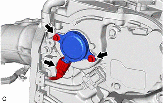
| (a) Disconnect the cam timing oil control solenoid assembly connector. |
|
(b)
Using an 8 mm socket wrench, remove the 2 bolts and cam timing oil
control solenoid assembly from the No. 2 timing chain cover assembly.
NOTICE:
If the cam timing oil control solenoid assembly has been struck or dropped, replace it.
3. REMOVE O-RING
HINT:
Perform this procedure only when replacement of the O-ring is necessary.
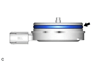
| (a) Remove the O-ring from the cam timing oil control solenoid assembly.
NOTICE:
- When removing the O-ring, be careful not to damage the O-ring groove of the cam timing oil control solenoid assembly.
- If the O-ring groove of the cam timing oil control solenoid assembly is
damaged, replace the cam timing oil control solenoid assembly with a new
one.
| |


