Transmission (Shaft) Mechanical Linkage Failure (P314779)
DTC SUMMARY
Refer to the DTC summary for DTC P1C7779.
Click here 
DESCRIPTION
Refer to the description for DTC P1C7779.
Click here

|
DTC No. | Detection Item |
DTC Detection Condition | Trouble Area |
MIL | Warning Indicate |
|
P314779 | Transmission (Shaft) Mechanical Linkage Failure |
Drive force from motor (MG2) or the engine cannot be transmitted to the wheels.
The
engine, generator (MG1), motor (MG2) or hybrid vehicle transaxle
assembly does not run smoothly due to a mechanical malfunction. (1 trip detection logic) |
- Hybrid vehicle transaxle assembly
- Transmission input damper assembly
- Engine
| Does not come on |
Master Warning Light: Comes on |
Related Data List |
DTC No. | Data List |
|
P314779 |
- Generator Revolution
- Motor Revolution
- Engine Speed
|
CONFIRMATION DRIVING PATTERN
HINT:
After
repair has been completed, clear the DTCs and then check that the
vehicle has returned to normal by performing the following All Readiness
check procedure.
Click here 
- Connect the Techstream to the DLC3.
- Turn the power switch on (IG) and turn the Techstream on.
- Clear the DTCs (even if no DTCs are stored, perform the clear DTC procedure).
- Turn the power switch off and wait for 2 minutes or more.
- Turn the power switch on (IG) and turn the Techstream on.
- Turn the power switch on (READY).
- Drive the vehicle at approximately 30 km/h (19 mph) or more for approximately 5 seconds or more using the engine.
- Enter the following menus: Powertrain / Hybrid Control / Utility / All Readiness.
- Check the DTC judgment result.
HINT:
- If the judgment result shows NORMAL, the system is normal.
- If the judgment result shows ABNORMAL, the system has a malfunction.
- If the judgment result shows INCOMPLETE or N/A, perform driving pattern again.
CAUTION / NOTICE / HINT
HINT:
- A seized engine, mechanical malfunction of the hybrid vehicle transaxle can be suspected.
- If this DTC is output, the engine or gears in the transaxle may have
seized or foreign matter have been caught in either of them. Therefore,
check the engine oil, hybrid transaxle fluid, coolant (for Engine) and
coolant (for Inverter) levels.
PROCEDURE
|
1. | CHECK DTC OUTPUT (ENGINE) |
(a) Connect the Techstream to the DLC3.
(b) Turn the power switch on (IG).
(c) Enter the following menus: Powertrain / Engine / Trouble Codes.
Powertrain > Engine > Trouble Codes
(d) Check for DTCs.
|
Result | Proceed to |
|
No DTCs are output, or DTCs except the ones in the table below are also output |
A |
| Any of the following DTCs are also output |
B |
|
Relevant DTC |
| P033511 |
Crankshaft Position Sensor "A" Circuit Short to Ground |
|
P033515 | Crankshaft Position Sensor "A" Circuit Short to Battery or Open |
|
P03352A | Crankshaft Position Sensor "A" Signal Stuck in Range |
|
P033531 | Crankshaft Position Sensor "A" No Signal |
(e) Turn the power switch off.
| B |  |
GO TO DTC CHART (SFI SYSTEM) |
|
A |
 | |
| 2. |
CHECK CRANKSHAFT PULLEY REVOLUTION (P POSITION) |
Click here 
| NG |
 | GO TO STEP 7 |
|
OK |
 | |
Click here

|
NEXT |
 | |
Click here

| NG |  |
REPLACE HYBRID VEHICLE TRANSAXLE ASSEMBLY |
|
OK |
 | |
Click here

| NG |  |
REPLACE HYBRID VEHICLE TRANSAXLE ASSEMBLY |
|
OK |
 | |
Click here

|
Result | Proceed to |
|
The absolute value of the difference is less than 500 rpm |
A |
| The absolute value of the difference is 500 rpm or more continuously for 1 second |
B |
| A |
 | REPLACE HYBRID VEHICLE TRANSAXLE ASSEMBLY |
| B |
 | REPLACE TRANSMISSION INPUT DAMPER ASSEMBLY |
| 7. |
CHECK CRANKSHAFT PULLEY REVOLUTION (N POSITION) |
Click here 
| OK |
 | REPLACE HYBRID VEHICLE TRANSAXLE ASSEMBLY |
| NG |
 | REPAIR OR REPLACE ENGINE |
Pattern Select Switch Eco Mode Circuit
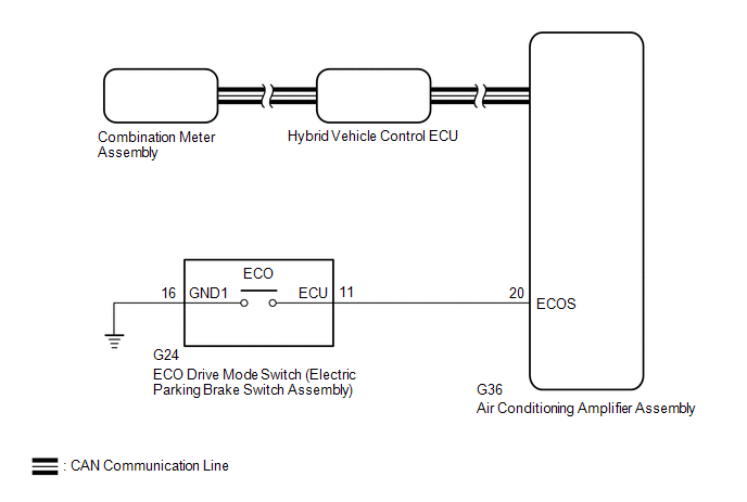
DESCRIPTION
When selecting
ECO drive mode, the ECO drive mode switch (electric parking brake switch
assembly) operation signal is sent to the air conditioning amplifier
assembly. Following this, ECO drive mode control is activated for the
heater and air conditioning system and the hybrid vehicle control
system.
WIRING DIAGRAM
PROCEDURE
| 1. |
READ VALUE USING TECHSTREAM (CAN BUS CHECK) |
Click here 
|
Result | Proceed to |
|
All of the ECUs and sensors that are currently connected to the CAN communication system are displayed |
A |
| None
of the ECUs and sensors that are currently connected to the CAN
communication system are displayed, or some of them are not displayed |
B |
| B |
 | GO TO CAN COMMUNICATION SYSTEM |
|
A |
 | |
| 2. |
CHECK DTC OUTPUT (HEALTH CHECK) |
Click here

|
Result | Proceed to |
|
No DTCs are output | A |
|
DTCs are output | B |
| B |
 | GO TO DTC CHART |
|
A |
 | |
| 3. |
READ VALUE USING TECHSTREAM (ECO SWITCH) |
(a) Connect the Techstream to the DLC3.
(b) Turn the power switch on (IG).
(c) Enter the following menus: Body Electrical / Air Conditioner / Data List / ECO Switch.
Body Electrical > Air Conditioner > Data List
|
Tester Display |
| ECO Switch |
(d) Read the value displayed on the Techstream.
Body Electrical > Air Conditioner > Data List
|
Tester Display | Measurement Item |
Range | Normal Condition |
|
ECO Switch | ECO drive mode switch condition |
ON or OFF | ECO drive mode switch being pushed and held: ON
ECO drive mode switch not operated: OFF |
|
Result | Proceed to |
|
The Techstream display changes according to the ECO drive mode switch operation |
A |
| The Techstream display does not change according to the ECO drive mode switch operation |
B |
| A |
 | REPLACE AIR CONDITIONING AMPLIFIER ASSEMBLY |
|
B |
 | |
| 4. |
INSPECT ECO DRIVE MODE SWITCH (ELECTRIC PARKING BRAKE SWITCH ASSEMBLY) |
Click here 
| NG |
 | REPLACE ELECTRIC PARKING BRAKE SWITCH ASSEMBLY |
|
OK |
 | |
| 5. |
CHECK HARNESS AND CONNECTOR (ECO DRIVE MODE SWITCH (ELECTRIC PARKING BRAKE SWITCH ASSEMBLY) - BODY GROUND) |
(a) Disconnect the G24 ECO drive mode switch (electric parking brake switch assembly) connector.
| (b) Measure the resistance according to the value(s) in the table below.
Standard Resistance: |
Tester Connection | Condition |
Specified Condition | |
G24-16 (GND1) - Body ground |
Always | Below 1 Ω | |
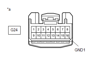 |
|
*a | Front view of wire harness connector
(to ECO Drive Mode Switch (Electric Parking Brake Switch Assembly)) | | |
(c) Reconnect the G24 ECO drive mode switch (electric parking brake switch assembly) connector.
| NG |
 | REPAIR OR REPLACE HARNESS OR CONNECTOR |
|
OK |
 | |
| 6. |
CHECK
HARNESS AND CONNECTOR (AIR CONDITIONING AMPLIFIER ASSEMBLY - ECO DRIVE
MODE SWITCH (ELECTRIC PARKING BRAKE SWITCH ASSEMBLY)) |
(a) Disconnect the G36 air conditioning amplifier assembly connector.
(b) Disconnect the G24 ECO drive mode switch (electric parking brake switch assembly) connector.
| (c) Measure the resistance according to the value(s) in the table below.
Standard Resistance: |
Tester Connection | Condition |
Specified Condition | |
G36-20 (ECOS) - G24-11 (ECU) |
Always | Below 1 Ω | |
G36-20 (ECOS) or G24-11 (ECU) - Body ground |
Always | 10 kΩ or higher | |
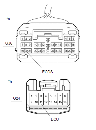 |
|
*a | Front view of wire harness connector
(to Air Conditioning Amplifier Assembly) | |
*b | Front view of wire harness connector
(to ECO Drive Mode Switch (Electric Parking Brake Switch Assembly)) | | |
(d) Reconnect the G24 ECO drive mode switch (electric parking brake switch assembly) connector.
(e) Reconnect the G36 air conditioning amplifier assembly connector.
| OK |
 | REPLACE AIR CONDITIONING AMPLIFIER ASSEMBLY |
| NG |
 | REPAIR OR REPLACE HARNESS OR CONNECTOR |


