DESCRIPTION
The hybrid vehicle control ECU monitors the system internal operation, it will store a DTC and perform fail-safe control if it detects the following malfunction.
|
DTC No. | Detection Item |
DTC Detection Condition | Trouble Area |
MIL | Warning Indicate |
|---|---|---|---|---|---|
|
P1C8549 | High Voltage Power Resource Internal Electronic Failure |
Battery overcurrent or overload current occurs due to a malfunction in the high-voltage circuit between the hybrid system, battery and inverter. (1 trip detection logic) |
| Does not come on |
Master Warning Light: Comes on |
|
DTC No. | Data List |
|---|---|
|
P1C8549 |
|
CONFIRMATION DRIVING PATTERN
HINT:
After repair has been completed, clear the DTC and then check that the vehicle has returned to normal by performing the following All Readiness check procedure.
Click here 
HINT:
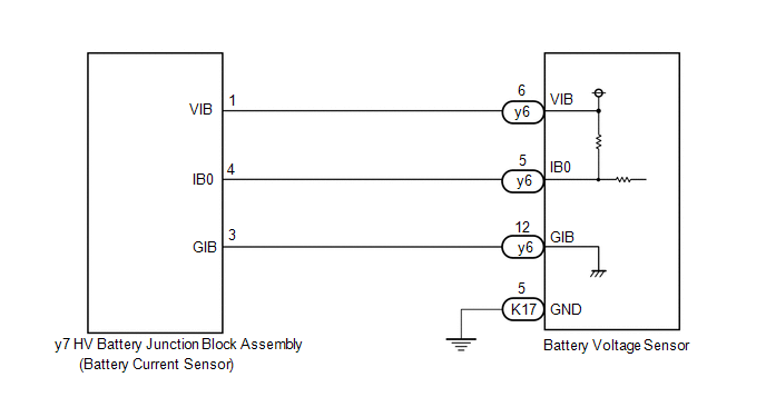
WIRING DIAGRAM
CAUTION / NOTICE / HINT
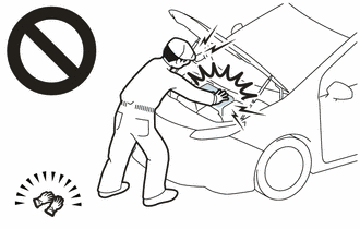
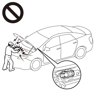
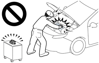
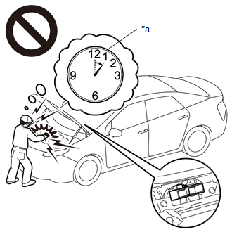
CAUTION:
|
*a |
Without waiting for 10 minutes |
Click here
HINT:
Waiting for at least 10 minutes is required to discharge the high-voltage capacitor inside the inverter with converter assembly.
NOTICE:
After turning the power switch off, waiting time may be required before disconnecting the cable from the negative (-) auxiliary battery terminal. Therefore, make sure to read the disconnecting the cable from the negative (-) auxiliary battery terminal notices before proceeding with work.
Click here
PROCEDURE
| 1. |
CHECK DTC OUTPUT (HYBRID CONTROL) |
(a) Connect the Techstream to the DLC3.
(b) Turn the power switch on (IG).
(c) Enter the following menus: Powertrain / Hybrid Control / Trouble Codes.
(d) Check for DTCs.
Powertrain > Hybrid Control > Trouble Codes|
Result | Proceed to |
|---|---|
|
P1C8549 only is output. |
A |
| DTCs other than P1C8549 is also output. |
B |
(e) Turn the power switch off.
| B |
 | GO TO DTC CHART (HYBRID CONTROL SYSTEM) |
|
| 2. |
READ VALUE USING TECHSTREAM (HYBRID BATTERY CURRENT) |
(a) Connect the Techstream to the DLC3.
(b) Turn the power switch on (IG).
(c) Enter the following menus: Powertrain / Hybrid Control / Data List / Hybrid Battery Current.
Powertrain > Hybrid Control > Data List|
Tester Display |
|---|
| Hybrid Battery Current |
(d) Read the Data List.
| Result |
Proceed to |
|---|---|
| The value of Hybrid Battery Current is between -4 A and 4 A |
A |
| Other than above |
B |
(e) Turn the power switch off.
| A |
| REPLACE HYBRID VEHICLE CONTROL ECU |
|
| 3. |
CHECK HARNESS AND CONNECTOR (BATTERY VOLTAGE SENSOR - HV BATTERY JUNCTION BLOCK ASSEMBLY) |
CAUTION:
Be sure to wear insulated gloves.
(a) Check that the service plug grip is not installed.
NOTICE:
After removing the service plug grip, do not turn the power switch on (READY), unless instructed by the repair manual because this may cause a malfunction.
(b) Remove the No. 1 HV battery cover panel RH.
Click here
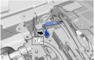
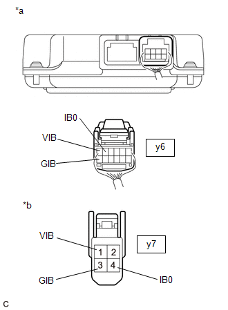
| (c) Disconnect the y7 battery current sensor connector. NOTICE: Before disconnecting the connector, check that it is not loose or disconnected. |
|
(d) Remove the No. 1 hybrid battery exhaust duct.
Click here
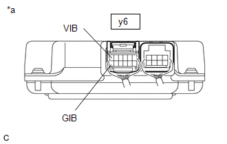
(e) Disconnect the y6 battery voltage sensor connector.
NOTICE:
Before disconnecting the connector, check that it is not loose or disconnected.
| (f) Measure the resistance according to the value(s) in the tables below. Standard Resistance (Check for Open):
Standard Resistance (Check for Short):
HINT: As the battery harness is not available as a supply part, if the harness cannot be repaired, replace the HV battery. |
|
(g) Reconnect the y6 battery voltage sensor connector.
(h) Install the No. 1 hybrid battery exhaust duct.
(i) Reconnect the y7 battery current sensor connector.
(j) Install the No. 1 HV battery cover panel RH.
| NG | | REPLACE HYBRID BATTERY THERMISTOR |
|
| 4. |
CHECK HV BATTERY JUNCTION BLOCK ASSEMBLY (BATTERY CURRENT SENSOR (IB)) |
CAUTION:
Be sure to wear insulated gloves.
(a) Check that the service plug grip is not installed.
NOTICE:
After removing the service plug grip, do not turn the power switch on (READY), unless instructed by the repair manual because this may cause a malfunction.
(b) Remove the No. 1 hybrid battery exhaust duct.
Click here
(c) Connect the cable to the negative (-) auxiliary battery terminal.
(d) Turn the power switch on (IG).
| (e) Using a toyota electrical tester set to 40 V, measure the VIB voltage according to the value(s) in the table below.
NOTICE:
|
|
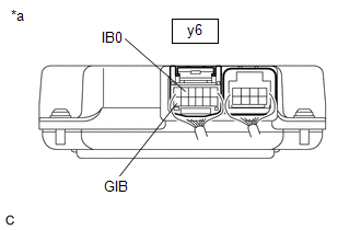
| (f) Using a toyota electrical tester set to 4 V, measure the IB0 voltage according to the value(s) in the table below.
NOTICE: Be sure to set the toyota electrical tester to 4 V when performing this test. |
|
(g) Compare the measured values of the IB0 terminal voltage and VIB terminal voltage using the following formula:
|
IB0 voltage - VIB Voltage / 2 = less than 0.081 V |
|
IB0 voltage - VIB Voltage / 2 = -0.081 V or higher |
|
Result | Proceed to |
|---|---|
|
Within the specified range above |
A |
| Other than above |
B |
(h) Turn the power switch off.
(i) Disconnect the cable from the negative (-) auxiliary battery terminal.
(j) Install the No. 1 hybrid battery exhaust duct.
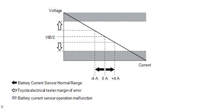
HINT:
When the power switch is on (IG) the actual current will be approximately 0 A. The following graph shows the relation of the actual output voltage of the battery current sensor terminal IB0 and actual current used for DTC judgment.
| B |
| REPLACE HV BATTERY JUNCTION BLOCK ASSEMBLY |
|
| 5. |
REPLACE BATTERY VOLTAGE SENSOR |
Click here
|
| 6. |
SIMULATION TEST |
(a) Connect the Techstream to the DLC3.
(b) Turn the power switch on (IG).
(c) Enter the following menus: Powertrain / Hybrid Control / Trouble Codes.
(d) Clear the DTCs and freeze frame data.
Powertrain > Hybrid Control > Clear DTCs(e) Drive the vehicle on urban roads for approximately 10 minutes.
(f) Turn the power switch off and wait for 2 minutes or more.
(g) Turn the power switch on (IG) and wait for 30 seconds or more.
|
| 7. |
RECONFIRM DTC OUTPUT (HYBRID CONTROL) |
(a) Connect the Techstream to the DLC3.
(b) Turn the power switch on (IG).
(c) Enter the following menus: Powertrain / Hybrid Control / Trouble Codes.
(d) Read output DTCs.
Powertrain > Hybrid Control > Trouble Codes(e) Turn the power switch off.
|
Result | Proceed to |
|---|---|
|
DTCs are not output | A |
|
P1C8549 is output | B |
| A |
| END |
| B |
| REPLACE HV BATTERY JUNCTION BLOCK ASSEMBLY |
Toyota Avalon (XX50) 2019-2022 Service & Repair Manual > Hybrid / Battery Control: Combination Switch
ComponentsCOMPONENTS ILLUSTRATION *1 ELECTRIC PARKING BRAKE SWITCH ASSEMBLY - - InspectionINSPECTION PROCEDURE 1. INSPECT ELECTRIC PARKING BRAKE SWITCH ASSEMBLY (a) Inspect EV mode switch (electric parking brake switch assembly) (1) Measure the resistance according to the value(s) in the table belo ...