Inverter "A" Cooling System Performance (P0A9300)
DTC SUMMARY
MALFUNCTION DESCRIPTION
This
DTC indicates when the temperature sensor value inside the inverter has
become abnormal. The cause of this malfunction may be one of the
following:
Internal inverter malfunction
- Inverter internal circuit malfunction
- Malfunction in ECU that controls the inverter
- Malfunction in sensor for inverter control (coolant temperature sensor)
Hybrid cooling system malfunction
- Coolant is leaking, insufficient coolant level, frozen or the passenger of coolant is clogged.
- Grille is blocked.
DESCRIPTION
Refer to the system description for the Cooling System.
Click here 
|
DTC No. | Detection Item |
DTC Detection Condition | Trouble Area |
MIL | Warning Indicate |
|
P0A9300 | Inverter "A" Cooling System Performance |
- Inverter coolant temperature increases as well as the temperature of any
inverter with converter assembly related parts due to an inverter
cooling system malfunction.
- When the actual temperature of the inverter coolant is higher than the
sensor value by a certain value or more and the actual temperature is
high.
(1 trip detection logic) |
- Inverter cooling system
- Inverter water pump assembly
- Inverter with converter assembly
- Cooling fan system
- Wire harness or connector
| Comes on |
Master Warning Light: Comes on |
Related Data List |
DTC No. | Data List |
|
P0A9300 |
- Inverter Coolant Water Temperature
- Motor Inverter Temperature
- Generator Inverter Calculated Temperature
- Boosting Converter Temperature (Upper)
- Boosting Converter Temperature (Lower)
- Inverter Water Pump Revolution
|
MONITOR DESCRIPTION
If
the hybrid vehicle control ECU detects a malfunction of the inverter
cooling system, the ECU will illuminate the MIL and store a DTC.
MONITOR STRATEGY
|
Related DTCs | P0A93 (INF P0A9300): HV cooling system malfunction |
|
Required sensors/components |
Water pump, radiator fan, inverter, boost converter |
|
Frequency of operation |
Continuous |
| Duration |
TMC's intellectual property |
|
MIL operation | 1 driving cycle |
|
Sequence of operation | None |
TYPICAL ENABLING CONDITIONS
|
The monitor will run whenever the following DTCs are not stored |
TMC's intellectual property |
|
Other conditions belong to TMC's intellectual property |
- |
TYPICAL MALFUNCTION THRESHOLDS
|
TMC's intellectual property |
- |
COMPONENT OPERATING RANGE
|
Hybrid vehicle control ECU |
DTC P0A93 (INF P0A9300) is not detected |
CONFIRMATION DRIVING PATTERN
HINT:
- After repair has been completed, clear the DTC and then check that the
vehicle has returned to normal by performing the following All Readiness
check procedure.
Click here
- When clearing the permanent DTCs, refer to the "CLEAR PERMANENT DTC" procedure.
Click here
- Connect the Techstream to the DLC3.
- Turn the power switch on (IG) and turn the Techstream on.
- Clear the DTCs (even if no DTCs are stored, perform the clear DTC procedure).
- Turn the power switch off and wait for 2 minutes or more.
- Turn the power switch on (IG) and turn the Techstream on.
- With power switch on (IG) and wait for 5 seconds or more. [*1]
- Turn the power switch on (READY) and wait for 5 seconds or more. [*2]
- Perform a road test according to the freeze frame data item "Vehicle Speed" for approximately 10 minutes. [*3]
NOTICE:
As
the state of charge of the HV battery voltage may be low after driving
in fail-safe mode, it will automatically be charged for 5 to 10 minutes
after repairs have been performed and turn the power switch on (READY).
HINT:
[*1] to [*3] : Normal judgment procedure.
The normal judgment procedure is used to complete DTC judgment and also used when clearing permanent DTCs.
- Enter the following menus: Powertrain / Hybrid Control / Utility / All Readiness.
- Check the DTC judgment result.
HINT:
- If the judgment result shows NORMAL, the system is normal.
- If the judgment result shows ABNORMAL, the system has a malfunction.
- If the judgment result shows INCOMPLETE or N/A, perform the normal judgment procedure again.
WIRING DIAGRAM
Refer to the wiring diagram for Cooling System.
Click here
CAUTION / NOTICE / HINT
CAUTION:
NOTICE:
After
turning the power switch off, waiting time may be required before
disconnecting the cable from the negative (-) auxiliary battery
terminal. Therefore, make sure to read the disconnecting the cable from
the negative (-) auxiliary battery terminal notices before proceeding
with work.
Click here
PROCEDURE
(a) Connect the Techstream to the DLC3.
(b) Turn the power switch on (IG).
(c) Enter the following menus: Powertrain / Hybrid Control, Motor Generator and Engine / Trouble Codes.
(d) Check for DTCs.
Powertrain > Hybrid Control > Trouble Codes Powertrain > Motor
Generator > Trouble Codes Powertrain > Engine > Trouble Codes
|
Result | Proceed to |
|
P0A9300 only is output, or DTCs except the ones in the table below are also output. |
A |
| DTCs of hybrid control system in the table below are output. |
B |
| DTCs of motor generator control system in the table below are output. |
C |
| DTCs of SFI system in the table below are output. |
D |
Table 1 |
Malfunction Content | System |
Relevant DTC |
|
Insulation malfunction |
Hybrid control system | P1C7C49 |
Hybrid/EV Battery Voltage System Isolation (A/C Area) Internal Electronic Failure |
|
P1C7D49 | Hybrid/EV Battery Voltage System Isolation (Hybrid/EV Battery Area) Internal Electronic Failure |
|
P1C7E49 | Hybrid/EV Battery Voltage System Isolation (Transaxle Area) Internal Electronic Failure |
|
P1C7F49 | Hybrid/EV Battery Voltage System Isolation (Direct Current Area) Internal Electronic Failure |
Table 2 |
Malfunction Content | System |
Relevant DTC |
|
Sensor and actuator circuit malfunction |
Hybrid control system | P0C7396 |
Motor Electronics Coolant Pump "A" Component Internal Failure |
|
P314A31 | Motor Electronics Coolant Pump "A" No Signal |
|
Motor generator control system |
P0A0011 | Motor Electronics Coolant Temperature Sensor Circuit Short to Ground |
|
P0A0015 | Motor Electronics Coolant Temperature Sensor Circuit Short to Battery or Open |
|
System malfunction |
SFI system | P059F73 |
Active Grille Air Shutter "A" Actuator Stuck Closed |
|
P05A072 | Active Grille Air Shutter "A" Actuator Stuck Open |
|
P05A074 | Active Grille Air Shutter "A" Actuator Slipping |
|
P05A211 | Active Grille Air Shutter "A" Circuit Short to Ground |
|
P05A212 | Active Grille Air Shutter "A" Circuit Short to Battery |
|
P05A213 | Active Grille Air Shutter "A" Circuit Open |
|
P05A27E | Active Grille Air Shutter "A" Actuator Stuck On |
|
P05A27F | Active Grille Air Shutter "A" Actuator Stuck Off |
|
P05B112 | Active Grille Air Shutter "B" Circuit Short to Battery |
|
P05B114 | Active Grille Air Shutter "B" Circuit Short to Ground or Open |
|
P05B131 | Active Grille Air Shutter "B" No Signal |
|
U028487 | Lost Communication with Active Grille Air Shutter Module "A" Missing Message |
HINT:
- P0A9300 may be output as a result of the malfunction indicated by the DTCs above.
- The chart above is listed in inspection order of priority.
- Check DTCs that are output at the same time by following the listed
order. (The main cause of the malfunction can be determined without
performing unnecessary inspections.)
(e) Turn the power switch off.
| B |
 | GO TO DTC CHART (HYBRID CONTROL SYSTEM) |
| C |
| GO TO DTC CHART (MOTOR GENERATOR CONTROL SYSTEM) |
| D |
| GO TO DTC CHART (SFI SYSTEM) |
|
A |
 | |
| 2. |
CHECK CONNECTOR CONNECTION CONDITION (INVERTER WITH CONVERTER ASSEMBLY CONNECTOR) |
Click here
|
Result | Proceed to |
|
OK | A |
|
NG (The connector is not connected securely.) |
B |
| NG (The terminals are not making secure contact or are deformed, or water or foreign matter exists in the connector.) |
C |
| B |
| CONNECT SECURELY |
| C |
| REPAIR OR REPLACE HARNESS OR CONNECTOR |
|
A | |
| |
Click here
HINT:
If the "Cooling System" inspection results are normal, perform the next step.
| NEXT |
| REPLACE HV COOLANT |
Hybrid/EV Battery Positive Contactor Circuit Stuck Closed (P0AA000)
DTC SUMMARY
MALFUNCTION DESCRIPTION
The
hybrid vehicle control ECU detects a stuck closed malfunction of a
system main relay on the HV battery positive (+) terminal side.
The cause of this malfunction may be one of the following:
Inverter voltage sensor (VH) internal circuit malfunction
- Voltage sensor (VH) malfunction
- Motor generator control ECU (MG ECU) malfunction
- Communication (wire harness) malfunction
High voltage system malfunction
- HV battery junction block assembly malfunction
Low-voltage circuit (12 V) malfunction
- Hybrid vehicle control ECU malfunction
- HV battery junction block assembly malfunction
- Low voltage wire harness malfunction
- Low voltage connector malfunction
DESCRIPTION
Refer to the description for DTC P0AE411.
Click here 
|
DTC No. | Detection Item |
DTC Detection Condition | Trouble Area |
MIL | Warning Indicate |
|
P0AA000 | Hybrid/EV Battery Positive Contactor Circuit Stuck Closed |
Even the system main relay of HV battery positive (+) terminal side is turned off, the inverter voltage (VH) does not drop.
(1 trip detection logic) |
- HV battery junction block assembly
- Inverter with converter assembly
- Hybrid vehicle control ECU
- Wire harness or connector
| Does not come on |
Master Warning Light: Comes on |
Related Data List |
DTC No. | Data List |
|
P0AA000 |
- Hybrid Battery Voltage
- VH-Voltage after Boosting
- VL-Voltage before Boosting
|
CONFIRMATION DRIVING PATTERN
HINT:
After
repair has been completed, clear the DTC and then check that the
vehicle has returned to normal by performing the following All Readiness
check procedure.
Click here
- Connect the Techstream to the DLC3.
- Turn the power switch on (IG) and turn the Techstream on.
- Clear the DTCs (even if no DTCs are stored, perform the clear DTC procedure).
- Turn the power switch off and wait for 2 minutes or more.
- Turn the power switch on (IG) and turn the Techstream on.
- Turn the power switch on (READY) and wait for 3 minutes or more.
HINT:
According
to the display on the Techstream, read the Data List and monitor the
values of "Hybrid Battery Voltage" and "VL-Voltage before Boosting" for 3
minutes. If the difference between "Hybrid Battery Voltage" and
"VL-Voltage before Boosting" is always less than 100 V, the vehicle has
returned to normal.
- Enter the following menus: Powertrain / Hybrid Control / Utility / All Readiness.
- Check the DTC judgment result.
HINT:
- If the judgment result shows NORMAL, the system is normal.
- If the judgment result shows ABNORMAL, the system has a malfunction.
- If the judgment result shows INCOMPLETE or N/A, perform driving pattern again.
WIRING DIAGRAM
Refer to the wiring diagram for the HV battery high-voltage line circuit.
Click here
CAUTION / NOTICE / HINT
CAUTION:
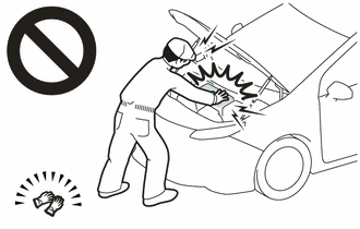
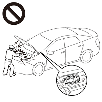
- Before the following operations are conducted, take precautions to
prevent electric shock by turning the power switch off, wearing
insulated gloves, and removing the service plug grip from HV battery.

- Inspecting the high-voltage system
- Disconnecting the low voltage connector of the inverter with converter assembly
- Disconnecting the low voltage connector of the HV battery
- To prevent electric shock, make sure to remove the service plug grip to
cut off the high voltage circuit before servicing the vehicle.
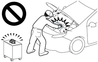
- After removing the service plug grip from the HV battery, put it in your
pocket to prevent other technicians from accidentally reconnecting it
while you are working on the high-voltage system.

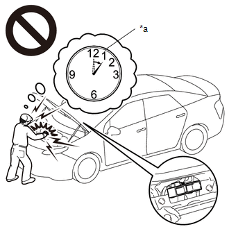
- After removing the service plug grip, wait for at least 10 minutes
before touching any of the high-voltage connectors or terminals. After
waiting for 10 minutes, check the voltage at the terminals in the
inspection point in the inverter with converter assembly. The voltage
should be 0 V before beginning work.
Click here
HINT:
Waiting for at least 10 minutes is required to discharge the high-voltage capacitor inside the inverter with converter assembly.

|
*a |
Without waiting for 10 minutes |
- Make sure to insulate the high-voltage connectors and terminals of the HV battery with insulating tape after removing it.
If the HV battery stored without insulating the connectors and terminals, electric shock or fire may result.
NOTICE:
- After turning the power switch off, waiting time may be required before
disconnecting the cable from the negative (-) auxiliary battery
terminal. Therefore, make sure to read the disconnecting the cable from
the negative (-) auxiliary battery terminal notices before proceeding
with work.
Click here
- If the DTCs are cleared or the cable is disconnected and reconnected to
the negative (-) auxiliary battery terminal before performing repairs,
turning the power switch on (READY) may cause a malfunction. Do not turn
the power switch on (READY).
HINT:
If DTC P0AA000 is output, the power switch cannot be turned on (READY).
PROCEDURE
| 1. |
CHECK DTC OUTPUT (HYBRID CONTROL, MOTOR GENERATOR) |
(a) Connect the Techstream to the DLC3.
(b) Turn the power switch on (IG).
(c) Enter the following menus: Powertrain / Hybrid Control and Motor Generator / Trouble Codes.
(d) Check for DTCs.
Powertrain > Hybrid Control > Trouble Codes Powertrain > Motor Generator > Trouble Codes
|
Result | Proceed to |
|
P0AA000 only is output, or DTCs except the ones in the table below are also output. |
A |
| DTCs of hybrid control system in the tables below are output. |
B |
| DTCs of motor generator control system in the tables below are output. |
C |
|
Malfunction Content | System |
Relevant DTC |
|
Microcomputer malfunction |
Hybrid control system | P060647 |
Hybrid/EV Powertrain Control Module Processor Watchdog / Safety MCU Failure |
|
P060687 | Hybrid/EV Powertrain Control Module Processor to Monitoring Processor Missing Message |
|
P060A47 | Hybrid/EV Powertrain Control Module Monitoring Processor Watchdog / Safety MCU Failure |
|
P060A87 | Hybrid/EV Powertrain Control Module Processor from Monitoring Processor Missing Message |
|
P0A1B49 | Drive Motor "A" Control Module Internal Electronic Failure |
|
P1C9E9F | Hybrid/EV System Reset Stuck Off |
|
Motor generator control system |
P0A1B1F | Generator Control Module Circuit Intermittent |
|
P0A1A47 | Generator Control Module Watchdog / Safety ÎĽC Failure |
|
P0A1A49 | Generator Control Module Internal Electronic Failure |
|
P1C2A1C | Generator A/D Converter Circuit Circuit Voltage Out of Range |
|
P1C2A49 | Generator A/D Converter Circuit Internal Electronic Failure |
|
P1C2B1C | Drive Motor "A" Control Module A/D Converter Circuit Voltage Out of Range |
|
P1C2B49 | Drive Motor "A" Control Module A/D Converter Circuit Internal Electronic Failure |
|
P1CAC49 | Generator Position Sensor Internal Electronic Failure |
|
P1CAD49 | Drive Motor "A" Position Sensor Internal Electronic Failure |
|
P1CAF38 | Generator Position Sensor REF Signal Cycle Malfunction Signal Frequency Incorrect |
|
P1CB038 | Drive Motor "A" Position Sensor REF Signal Frequency Incorrect |
|
P313383 | Communication Error from Generator to Drive Motor "A" Value of Signal Protection Calculation Incorrect |
|
P313386 | Communication Error from Generator to Drive Motor "A" Signal Invalid |
|
P313387 | Communication Error from Generator to Drive Motor "A" Missing Message |
|
Power source circuit malfunction |
Motor generator control system | P06D61C |
Generator Control Module Offset Power Circuit Voltage Out of Range |
|
P06B01C | Generator Control Module Position Sensor REF Power Source Circuit Voltage Out of Range |
|
Communication system malfunction | Hybrid control system |
P312387 | Lost Communication with Drive Motor Control Module "A" from Hybrid/EV Control Module Missing Message |
|
Sensor and actuator circuit malfunction |
Hybrid control system | P0AD911 |
Hybrid/EV Battery Positive Contactor Circuit Short to Ground |
|
P0AD915 | Hybrid/EV Battery Positive Contactor Circuit Short to Auxiliary Battery or Open |
|
P0ADD11 | Hybrid/EV Battery Negative Contactor Circuit Short to Ground |
|
P0ADD15 | Hybrid/EV Battery Negative Contactor Circuit Short to Auxiliary Battery or Open |
|
P0AE411 | Hybrid/EV Battery Precharge Contactor Circuit Short to Ground |
|
P0AE415 | Hybrid/EV Battery Precharge Contactor Circuit Short to Auxiliary Battery or Open |
|
Motor generator control system | P0A3F16 |
Drive Motor "A" Position Sensor Circuit Voltage Below Threshold |
|
P0A4B16 | Generator Position Sensor Circuit Voltage Below Threshold |
|
P0A4B21 | Generator Position Sensor Signal Amplitude < Minimum |
|
P0A4B22 | Generator Position Sensor Signal Amplitude > Maximum |
|
P0C5013 | Drive Motor "A" Position Sensor Circuit "A" Circuit Open |
|
P0C5016 | Drive Motor "A" Position Sensor Circuit "A" Circuit Voltage Below Threshold |
|
P0C5017 | Drive Motor "A" Position Sensor Circuit "A" Circuit Voltage Above Threshold |
|
P0C5A13 | Drive Motor "A" Position Sensor Circuit "B" Circuit Open |
|
P0C5A16 | Drive Motor "A" Position Sensor Circuit "B" Circuit Voltage Below Threshold |
|
P0C5A17 | Drive Motor "A" Position Sensor Circuit "B" Circuit Voltage Above Threshold |
|
P0C6413 | Generator Position Sensor Circuit "A" Circuit Open |
|
P0C6416 | Generator Position Sensor Circuit "A" Circuit Voltage Below Threshold |
|
P0C6417 | Generator Position Sensor Circuit "A" Circuit Voltage Above Threshold |
|
P0C6913 | Generator Position Sensor Circuit "B" Circuit Open |
|
P0C6916 | Generator Position Sensor Circuit "B" Circuit Voltage Below Threshold |
|
P0C6917 | Generator Position Sensor Circuit "B" Circuit Voltage Above Threshold |
|
System malfunction | Hybrid control system |
P0D2D1C | Drive Motor "A" Inverter Voltage Sensor Voltage Out of Range |
|
P1C8349 | High Voltage Power Resource Circuit Voltage Sensor after Boosting Malfunction |
|
P0C7600 | Hybrid/EV Battery System Discharge Time Too Long |
|
Motor generator control system | P0D2D16 |
Drive Motor "A" Inverter Voltage Sensor (VH) Circuit Voltage Below Threshold |
|
P0D2D17 | Drive Motor "A" Inverter Voltage Sensor (VH) Circuit Voltage Above Threshold |
|
P1CB69E | Drive Motor "A" Inverter Voltage Sensor (VH) Stuck On |
HINT:
- P0AA000 may be output as a result of the malfunction indicated by the DTCs above.
- The chart above is listed in inspection order of priority.
- Check DTCs that are output at the same time by following the listed
order. (The main cause of the malfunction can be determined without
performing unnecessary inspections.)
(e) Turn the power switch off.
| B |
 | GO TO DTC CHART (HYBRID CONTROL SYSTEM) |
| C |
| GO TO DTC CHART (MOTOR GENERATOR CONTROL SYSTEM) |
|
A |
 | |
| 2. |
CHECK FREEZE FRAME DATA (HYBRID CONTROL) |
(a) Connect the Techstream to the DLC3.
(b) Turn the power switch on (IG).
(c) Enter the following menus: Powertrain / Hybrid Control / Trouble Codes.
(d) Read the freeze frame data of DTC P0AA000.
Powertrain > Hybrid Control > Trouble Codes
NOTICE:
As
freeze frame data is stored immediately before and after a DTC is
stored, make sure to only read the values for the moment the DTC was
stored ("0(s)").
|
Result | Proceed to |
|
Difference between "VL-Voltage before Boosting" and "VH-Voltage after Boosting" is less than 76 V. |
A |
| Difference between "VL-Voltage before Boosting" and "VH-Voltage after Boosting" is 76 V or more. |
B |
HINT:
If
VH-Voltage after Boosting is output even when an off command is being
sent to the system main relay (positive side), P0AA000 is output. If the
difference between the "VL-Voltage before Boosting" and the "VH-Voltage
after Boosting" is large, it is determined that there is an inverter
(VH sensor) malfunction.
(e) Turn the power switch off.
| B |
| REPLACE INVERTER WITH CONVERTER ASSEMBLY |
|
A | |
| |
| 3. |
CHECK CONNECTOR CONNECTION CONDITION (HYBRID VEHICLE CONTROL ECU CONNECTOR) |
Click here
| OK |
| GO TO STEP 5 |
|
NG | |
| |
|
NEXT | |
| |
| 5. |
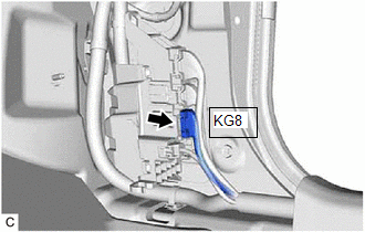
CHECK CONNECTOR CONNECTION CONDITION (FLOOR WIRE CONNECTOR) |
| (a)
Check the connection condition of the KG8 floor wire connector and the
contact pressure of each terminal. Check the terminals for deformation,
and check the connector for water ingress and foreign matter. Click here
OK: - The connector is connected securely.
- The terminals are not deformed and are connected securely. - No water or foreign matter in the connector. |
|
|
Result | Proceed to |
|
OK | A |
|
NG (The connector is not connected securely.) |
B |
| NG (The terminals are not making secure contact or are deformed, or water or foreign matter exists in the connector.) |
C |
| A |
| GO TO STEP 8 |
| C |
| GO TO STEP 7 |
|
B | |
| |
| NEXT |
| GO TO STEP 8 |
| 7. |
REPAIR OR REPLACE HARNESS OR CONNECTOR |
|
NEXT | |
| |
| 8. |
CHECK CONNECTOR CONNECTION CONDITION (HV BATTERY JUNCTION BLOCK ASSEMBLY CONNECTOR) |
CAUTION:
Be sure to wear insulated gloves.
(a) Check that the service plug grip is not installed.
NOTICE:
After
removing the service plug grip, do not turn the power switch on
(READY), unless instructed by the repair manual because this may cause a
malfunction.
(b) Remove the No. 1 HV battery cover panel RH.
Click here
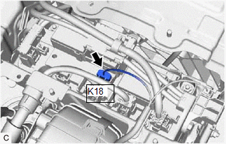
| (c)
Check the connector connections and contact pressure of the relevant
terminals of the K18 HV battery junction block assembly connector. Click here
OK: The connectors are connected securely and there are no contact pressure problems. |
|
(d) Install the No. 1 HV battery cover panel RH.
| OK |
| GO TO STEP 10 |
|
NG | |
| |
|
NEXT | |
| |
| 10. |
CHECK GROUND WIRE CONNECTION CONDITION (SMR ACTIVATION LOW-VOLTAGE CIRCUIT) |
(a) Check the installation condition of the ground wire KA.
OK:
The ground wire KA is securely installed.
| OK |
| GO TO STEP 12 |
|
NG | |
| |
|
NEXT | |
| |
| 12. |
CHECK HARNESS AND CONNECTOR (HYBRID VEHICLE CONTROL ECU - HV BATTERY JUNCTION BLOCK ASSEMBLY) |
CAUTION:
Be sure to wear insulated gloves.
(a) Check that the service plug grip is not installed.
NOTICE:
After
removing the service plug grip, do not turn the power switch on
(READY), unless instructed by the repair manual because this may cause a
malfunction.
(b) Remove the No. 1 HV battery cover panel RH.
Click here
(c) Disconnect the K18 HV battery junction block assembly connector.
(d) Disconnect the G46 hybrid vehicle control ECU connector.
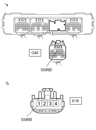
| (e) Measure the resistance according to the value(s) in the table below.
Standard Resistance (Check for Open): |
Tester Connection | Condition |
Specified Condition | |
G46-4 (SMRB) - K18-1 (SMRB) |
Power switch off |
Below 1 Ω | Standard Resistance (Check for Short): |
Tester Connection | Condition |
Specified Condition | |
G46-4 (SMRB) or K18-1 (SMRB) - Body ground and other terminals |
Power switch off |
10 kΩ or higher | |
 |
|
*a | Rear view of wire harness connector
(to Hybrid Vehicle Control ECU) | |
*b | Front view of wire harness connector
(to HV Battery Junction Block Assembly) | | |
(f) Reconnect the G46 hybrid vehicle control ECU connector.
(g) Reconnect the K18 HV battery junction block assembly connector.
(h) Install the No. 1 HV battery cover panel RH.
| OK |
| GO TO STEP 14 |
|
NG | |
| |
| 13. |
REPAIR OR REPLACE HARNESS OR CONNECTOR |
|
NEXT | |
| |
| 14. |
CHECK HARNESS AND CONNECTOR (HV BATTERY JUNCTION BLOCK ASSEMBLY - BODY GROUND) |
CAUTION:
Be sure to wear insulated gloves.
(a) Check that the service plug grip is not installed.
NOTICE:
After
removing the service plug grip, do not turn the power switch on
(READY), unless instructed by the repair manual because this may cause a
malfunction.
(b) Remove the No. 1 HV battery cover panel RH.
Click here
(c) Disconnect the K18 HV battery junction block assembly connector.
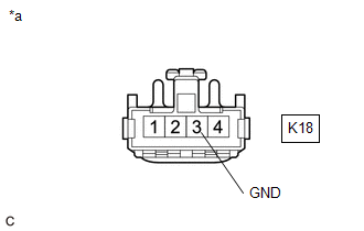
| (d) Measure the resistance according to the value(s) in the table below.
Standard Resistance: |
Tester Connection | Condition |
Specified Condition | |
K18-3 (GND) - Body ground |
Power switch off |
Below 1 Ω | |
 |
|
*a | Front view of wire harness connector
(to HV Battery Junction Block Assembly) | | |
(e) Reconnect the K18 HV battery junction block assembly connector.
(f) Install the No. 1 HV battery cover panel RH.
| OK |
| GO TO STEP 16 |
|
NG | |
| |
| 15. |
REPAIR OR REPLACE HARNESS OR CONNECTOR |
|
NEXT | |
| |
| 16. |
INSPECT HV BATTERY JUNCTION BLOCK ASSEMBLY (SMRB) |
CAUTION:
Be sure to wear insulated gloves.
(a) Check that the service plug grip is not installed.
NOTICE:
After
removing the service plug grip, do not turn the power switch on
(READY), unless instructed by the repair manual because this may cause a
malfunction.
(b) Remove the No. 1 HV battery cover panel RH.
Click here
(c) Disconnect the K18 HV battery junction block assembly connector.
(d) Measure the resistance according to the value(s) in the table below.
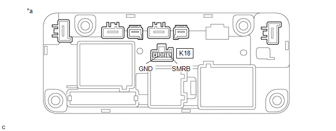
|
*a | Component without harness connected (HV Battery Junction Block Assembly) |
- | - |
Standard Resistance:
|
Tester Connection | Condition |
Specified Condition |
|
K18-1 (SMRB) - K18-3 (GND) |
-40 to 80°C (-40 to 176°F) |
25.0 to 59.0 Ω |
(e) Reconnect the K18 HV battery junction block assembly connector.
(f) Install the No. 1 HV battery cover panel RH.
| NG |
| GO TO STEP 19 |
|
OK | |
| |
| 17. |
CHECK HV BATTERY JUNCTION BLOCK ASSEMBLY (SMRB) |
CAUTION:
Be sure to wear insulated gloves.
(a) Check that the service plug grip is not installed.
NOTICE:
After
removing the service plug grip, do not turn the power switch on
(READY), unless instructed by the repair manual because this may cause a
malfunction.
(b) Remove the No. 1 HV battery cover panel RH.
Click here
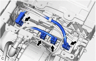
| (c) Disconnect the 2 HV floor under wire connectors from the HV battery junction block assembly. |
|
(d) Disconnect the 2 HV battery high voltage connectors from the HV battery junction block assembly.
NOTICE:
Insulate
each disconnected high-voltage connector with insulating tape. Wrap the
connector from the wire harness side to the end of the connector.
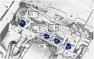
| (e) Measure the resistance according to the value(s) in the table below.
Standard Resistance: |
Tester Connection | Condition |
Specified Condition | |
S2-1 (CBI) - y5-1 (+) |
Power switch off |
10 kΩ or higher |
HINT:
- If a system main relay is stuck closed, inspect the HV battery junction
block assembly without removing it from the vehicle, in order to keep
the relay closed.
- If the result of reading the freeze frame data is A, the HV battery
junction block assembly must be replaced. Measuring resistance can
determine that this is either a present or past malfunction.
|
 |
|
*a | Component without harness connected
(HV Battery Junction Block Assembly) | | |
(f) Reconnect the 2 HV battery high voltage connectors.
(g) Reconnect the 2 HV floor under wire connectors.
(h) Install the No. 1 HV battery cover panel RH.
|
Result | Judgment |
Proceed to |
| OK |
Past malfunction | A |
|
NG | Present malfunction |
B |
| B |
| GO TO STEP 20 |
|
A | |
| |
| 18. |
REPLACE HV BATTERY JUNCTION BLOCK ASSEMBLY |
Click here
| NEXT |
| GO TO STEP 21 |
| 19. |
REPLACE HV BATTERY JUNCTION BLOCK ASSEMBLY |
Click here
| NEXT |
| GO TO STEP 21 |
| 20. |
REPLACE HV BATTERY JUNCTION BLOCK ASSEMBLY |
Click here
|
NEXT | |
| |
| 21. |
CHECK HYBRID VEHICLE CONTROL ECU (CHECK FOR NORMAL OPERATION) |
CAUTION:
Be sure to wear insulated gloves.
(a) Install the service plug grip.
(b) Turn the power switch on (IG).
(c) Clear the DTCs.
Click here
(d) Turn the power switch off and wait for 2 minutes or more.
(e) Turn the power switch on (READY).
(f) Enter the following menus: Powertrain / Hybrid Control / Data List / Hybrid Battery Voltage, VL-Voltage before Boosting.
(g)
According to the display on the Techstream, read the Data List and
monitor the values of "Hybrid Battery Voltage" and "VL-Voltage before
Boosting" for 3 minutes.
Powertrain > Hybrid Control > Data List
|
Tester Display |
| VL-Voltage before Boosting |
|
Hybrid Battery Voltage |
|
Result | Proceed to |
|
Difference between "Hybrid Battery Voltage" and "VL-Voltage before Boosting" is always less than 100 V. |
A |
| Difference between "Hybrid Battery Voltage" and "VL-Voltage before Boosting" is 100 V or more. |
B |
(h) Turn the power switch off.
| A |
| END |
| B |
| REPLACE HYBRID VEHICLE CONTROL ECU AND HV BATTERY JUNCTION BLOCK ASSEMBLY |