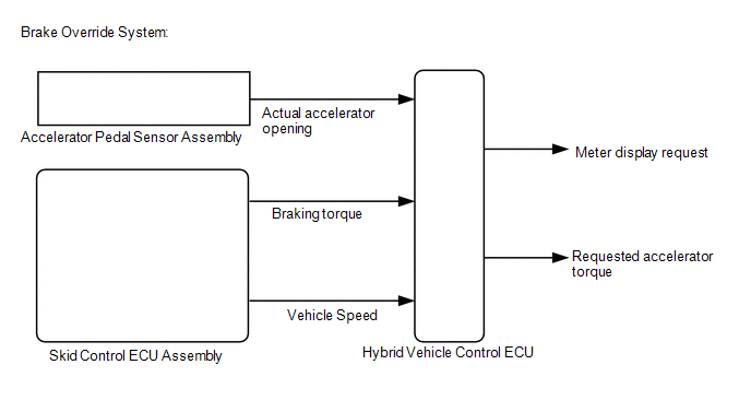
Brake Override System
DESCRIPTION
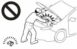
When the
vehicle is being driven with the accelerator pedal depressed, depressing
the brake pedal without releasing the accelerator pedal will activate
the brake override system to restrict driving torque. The conditions for
activating the brake override system as well as the items that are
controlled are explained below.
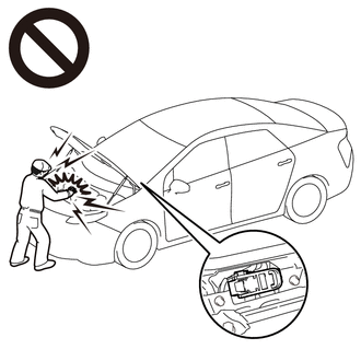
 Activation Conditions:
Items Controlled:
Activation Conditions:
Items Controlled:
- Controls driving torque
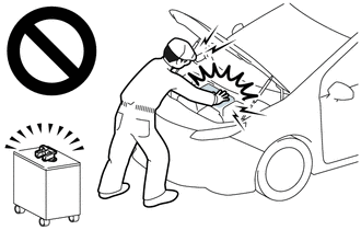
HINT:
- When the control is operating, requested accelerator torque is controlled in accordance with the brake pedal stroke.
- When the driving torque is reduced to a specified level because the
accelerator pedal and brake pedal are depressed at the same time, an
indicator is displayed on the meter. (Operation of the system can be
confirmed when the indicator is displayed on the meter.)
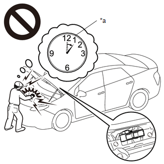
Deactivation Conditions:
- The accelerator pedal or brake pedal is released.
CAUTION / NOTICE / HINT
Inspection Method
Drive
at 10 km/h (6 mph), depress the accelerator pedal by 1/2 to 3/4 and
keep it in that position. Under these conditions, if driving torque is
controlled when the brake pedal is depressed by the left foot of the
driver, it can be confirmed that the brake override system has operated.
CAUTION:
Perform this road test only in an appropriate safe location, in accordance with all local laws.
Pay careful attention to the surroundings when performing the road test.
HINT:
The
brake override system restricts requested accelerator torque if the
brake pedal is depressed when driving with the accelerator pedal
depressed. If a customer reports experiencing a loss of power (requested
accelerator torque) after the accelerator and brake pedals have both
been intentionally depressed, explain that this is not a malfunction,
and depressing both the accelerator and brake pedals at the same time
should be avoided.
PROCEDURE
| 1. |
CHECK DTC OUTPUT (HEALTH CHECK) |
(a) Connect the Techstream to the DLC3.
(b) Turn the power switch on (IG).
(c) Turn the Techstream on.
(d) Enter the following menus: System Select / Health Check.
(e) Check for DTCs.
|
Result | Proceed to |
|
No DTCs are output | A |
|
DTCs are output | B |
(f) Turn the power switch off.
| B |  |
GO TO DTC CHART |
|
A |
 | |
| 2. |
READ VALUE USING TECHSTREAM (MASTER CYLINDER CONTROL TORQUE) |
(a) Connect the Techstream to the DLC3.
(b) Turn the power switch on (READY).
(c) Turn the Techstream on.
(d) Enter the following menus: Powertrain / Hybrid Control / Data List / Master Cylinder Control Torque.
Powertrain > Hybrid Control > Data List
|
Tester Display |
| Master Cylinder Control Torque |
(e) Read the value displayed on the Techstream.
|
Result | Proceed to |
|
Display changes according to brake pedal depression force |
A |
| Other than above |
B |
(f) Turn the power switch off.
| B |
| CHECK BRAKE BOOSTER WITH MASTER CYLINDER ASSEMBLY |
|
A | |
| |
| 3. |
READ VALUE USING TECHSTREAM (ACCELERATOR POSITION SENSOR NO. 1 VOLTAGE %, ACCELERATOR POSITION SENSOR NO. 2 VOLTAGE %) |
(a) Connect the Techstream to the DLC3.
(b) Turn the power switch on (IG).
(c) Turn the Techstream on.
(d)
Enter the following menus: Powertrain / Hybrid Control / Data List /
Accelerator Position Sensor No. 1 Voltage %, Accelerator Position Sensor
No. 2 Voltage %.
Powertrain > Hybrid Control > Data List
|
Tester Display |
| Accelerator Position Sensor No.1 Voltage % |
|
Accelerator Position Sensor No.2 Voltage % |
(e) Read the values displayed on the Techstream.
Standard:
|
Inspection Condition | Specified Condition |
|
Accelerator pedal fully released → fully depressed |
Value (%) changes with accelerator pedal operation |
(f) Turn the power switch off.
| NG | |
REPLACE ACCELERATOR PEDAL SENSOR ASSEMBLY |
|
OK | |
| |
| 4. |
READ VALUE USING TECHSTREAM (VEHICLE SPEED) |
(a) Connect the Techstream to the DLC3.
(b) Turn the power switch on (READY).
(c) Turn the Techstream on.
(d) Enter the following menus: Powertrain / Hybrid Control / Data List / Vehicle Speed.
Powertrain > Hybrid Control > Data List
|
Tester Display |
| Vehicle Speed |
(e) Read the value displayed on the Techstream.
Standard:
|
Inspection Condition | Specified Condition |
|
Vehicle stopped | 0 km/h (0 mph) |
|
Vehicle being driven at a constant speed (16 to 64 km/h (10 to 40 mph)) |
No large fluctuations in displayed speed |
CAUTION:
Perform this road test only in an appropriate safe location, in accordance with all local laws.
HINT:
Data
can be captured relatively easily by using the snapshot function in the
Data List. Confirm the data after performing the drive test.
(f) Turn the power switch off.
| NG |
| GO TO METER / GAUGE SYSTEM (SPEED SIGNAL CIRCUIT) |
|
OK | |
| |
| 5. |
READ VALUE USING TECHSTREAM (FR, FL, RR, RL WHEEL SPEED) |
(a) Connect the Techstream to the DLC3.
(b) Turn the power switch on (READY).
(c) Turn the Techstream on.
(d)
Enter the following menus: Chassis / ABS/VSC/TRAC / Data List / FR
Wheel Speed, FL Wheel Speed, RR Wheel Speed and RL Wheel Speed.
Chassis > ABS/VSC/TRAC > Data List
|
Tester Display |
| FR Wheel Speed |
|
FL Wheel Speed |
| RR Wheel Speed |
|
RL Wheel Speed |
(e) Read the values displayed on the Techstream.
Standard:
|
Inspection Condition | Specified Condition |
|
Vehicle stopped | 0 km/h (0 mph) |
|
Vehicle being driven at a constant speed (16 to 64 km/h (10 to 40 mph)) |
No large fluctuations in displayed speed |
CAUTION:
Perform this road test only in an appropriate safe location, in accordance with all local laws.
HINT:
Data
can be captured relatively easily by using the snapshot function in the
Data List. Confirm the data after performing the drive test.
(f) Turn the power switch off.
| OK |
| END |
| NG |
| INSPECT FRONT OR REAR SPEED SENSOR |
Cooling System
DESCRIPTION
The cause of the malfunction may be the cooling system.
Check
whether the grille is blocked, whether coolant is leaking, the radiator
fan operating condition and whether coolant has frozen.
Related Parts Check |
Area | Inspection |
|
Grille blockage, coolant amount, coolant hoses, radiator fan |
Check for overheating due to hybrid cooling system malfunction. |
|
Inverter coolant temperature sensor (built-in inverter) |
Check for temperature sensor malfunction. |
|
Coolant freezing check | Check freeze frame values to determine whether the hybrid coolant was frozen when the DTC was stored. |
Related Data List |
Data List |
- Inverter Coolant Water Temperature
- Motor Inverter Temperature
- Generator Inverter Calculated Temperature
- Boosting Converter Temperature (Upper)
- Boosting Converter Temperature (Lower)
- Ambient Temperature
- Inverter Water Pump Revolution
|
SYSTEM DESCRIPTION
The
inverter converts the high-voltage direct current of the HV battery
into alternating current for the generator (MG1) and motor (MG2). The
inverter generates heat during the conversion process. Therefore, the
inverter is cooled by a special cooling system consisting of the
inverter water pump assembly, the cooling fan, and a radiator. This
cooling system is independent of the engine cooling system. The hybrid
vehicle control ECU monitors the inverter water pump assembly, cooling
fan and cooling system, and detects malfunctions.
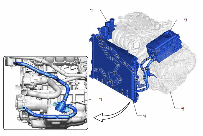
|
*1 | Inverter Water Pump Assembly |
*2 | Inverter Reserve Tank Assembly |
|
*3 | Inverter with Converter Assembly |
*4 | Radiator Assembly (HV) |
|
*5 | Hybrid Vehicle Transaxle Assembly |
- | - |
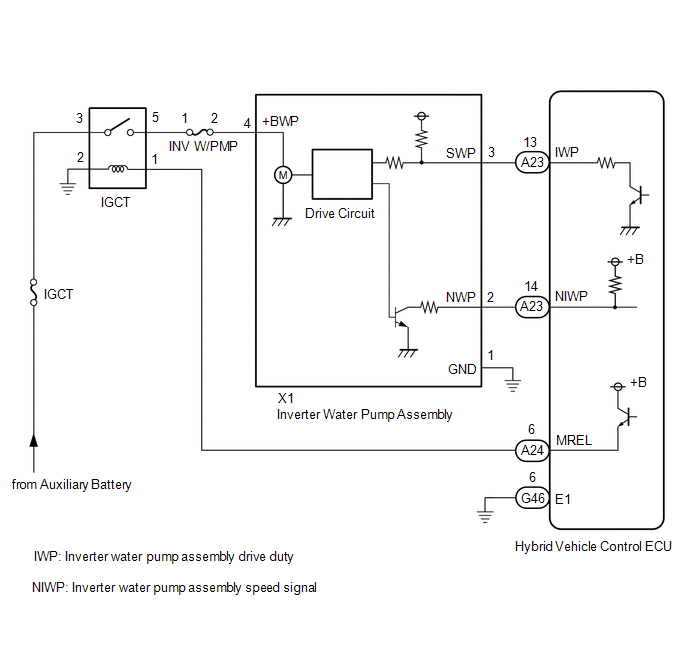
WIRING DIAGRAM
CAUTION / NOTICE / HINT
This diagnostic procedure is referenced to in the diagnostic procedure of several DTCs.
If the result of this diagnostic procedure is normal, proceed as directed in the procedure for the DTC.
CAUTION:
NOTICE:
After
turning the power switch off, waiting time may be required before
disconnecting the cable from the negative (-) auxiliary battery
terminal. Therefore, make sure to read the disconnecting the cable from
the negative (-) auxiliary battery terminal notices before proceeding
with work.
Click here 
PROCEDURE
| 1. |
CHECK VEHICLE CONDITION |
(a) Make sure that the front side of the radiator grille is not blocked with anything.
(b) Ask the customer if the front side of the radiator grille was blocked with anything.
| Result |
Proceed to |
| Not blocked. |
A |
| Is/was blocked. |
B |
HINT:
If the radiator grille is blocked, the inverter coolant temperature will increase and this DTC may be stored.
| B |
 | IF EQUIPPED, EXPLAIN TO CUSTOMER THAT OPTIONAL COMPONENTS WILL BE REMOVED |
|
A |
 | |
| 2. |
CHECK QUANTITY OF HV COOLANT |
(a) Check the HV coolant level in the inverter reserve tank.
(b) Check for HV coolant leaks.
|
Result | Proceed to |
|
No leaks are found and the HV coolant level in the inverter reserve tank assembly is above the low line. |
A |
| No leaks are found and the HV coolant level in the inverter reserve tank assembly is below the low line. |
B |
| HV coolant leaks are evident. |
C |
HINT:
- After repairing the HV coolant leaks and adding coolant, perform the
Active Tests "Activate the Inverter Water Pump" (Hybrid Control System)
and "Control the Cooling Fan Duty Ratio" (Engine Control System) and
make sure that there are no malfunctions.
- If there are signs of coolant leakage around the connecting parts of a
hose and the inverter with converter assembly, replace the hose with a
new one.
| B |
| ADD HV COOLANT |
| C |
| INSPECT FOR COOLANT LEAK AND ADD COOLANT |
|
A | |
| |
(a) Check that the cooling system hoses are not kinked or clogged.
OK:
The cooling system hoses are not kinked or clogged.
| NG |
| REPAIR OR REPLACE COOLANT HOSE |
|
OK | |
| |
| 4. |
PERFORM ACTIVE TEST USING TECHSTREAM (CONTROL THE ENGINE COOLING FAN DUTY RATIO) |
(a) Connect the Techstream to the DLC3.
(b) Turn the power switch on (IG).
(c) Enter the following menus: Powertrain / Engine / Active Test / Control the Engine Cooling Fan Duty Ratio.
Powertrain > Engine > Active Test
|
Tester Display |
| Control the Engine Cooling Fan Duty Ratio |
(d) Perform the "Control the Engine Cooling Fan Duty Ratio" Active Test.
OK:
| Techstream Operation |
Fan Operation |
| 30 - 100% |
Cooling fan operates |
| 0% |
Cooling fan stops |
| Result |
Proceed to |
| Cooling fan operate |
A |
| Cooling fan does not operate |
B |
| Cooling fan do not stop |
(e) Turn the power switch off.
| B | |
CHECK COOLING FAN SYSTEM |
|
A | |
| |
| 5. |
PERFORM ACTIVE TEST USING TECHSTREAM (GRILLE SHUTTER OPERATION) |
(a) Connect the Techstream to the DLC3.
(b) Turn the power switch on (IG).
(c) Enter the following menus: Body Electrical / Grill Shutter / Utility / Grill Shutter Control Mode Switching.
(d) According to the display on the Techstream, change the grille shutter control mode from normal mode to maintenance mode.
Body Electrical > Grill Shutter > Utility
|
Tester Display |
| Grill Shutter Control Mode Switching |
(e)
Enter the following menus: Body Electrical / Grill Shutter / Active
Test / Shutter Closing Operation Lock Detection / Data List / Shutter
Operation Lock Detection Result for Active Test.
(f)
According to the display on the Techstream, perform the Active Test and
read the value of Data List item Shutter Operation Lock Detection
Result for Active Test.
Body Electrical > Grill Shutter > Active Test
|
Active Test Display |
|
Shutter Closing Operation Lock Detection |
|
Data List Display |
|
Shutter Operation Lock Detection Result for Active Test |
OK:
"Normal" is displayed.
(g)
Enter the following menus: Body Electrical / Grill Shutter / Active
Test / Shutter Opening Operation Lock Detection / Data List / Shutter
Operation Lock Detection Result for Active Test.
(h)
According to the display on the Techstream, perform the Active Test and
read the value of Data List item Shutter Operation Lock Detection
Result for Active Test.
Body Electrical > Grill Shutter > Active Test
|
Active Test Display |
|
Shutter Opening Operation Lock Detection |
|
Data List Display |
|
Shutter Operation Lock Detection Result for Active Test |
OK:
"Normal" is displayed.
HINT:
When
the value of Data List item Shutter Operation Lock Detection Result for
Active Test is "Normal", it can be determined that the grille shutter
system is normal.
(i) Enter the following menus: Body Electrical / Grill Shutter / Utility / Grill Shutter Control Mode Switching.
(j) According to the display on the Techstream, change the grille shutter control mode from maintenance mode to normal mode.
Body Electrical > Grill Shutter > Utility
|
Tester Display |
| Grill Shutter Control Mode Switching |
(k) Turn the power switch off.
| NG | |
CHECK GRILLE SHUTTER SYSTEM |
|
OK | |
| |
| 6. |
PERFORM ACTIVE TEST USING TECHSTREAM (ACTIVATE THE INVERTER WATER PUMP) |
NOTICE:
- Make sure that the HV coolant level is above the low line of the inverter reserve tank.
- Be sure to perform the inspection with the auxiliary battery voltage at 11 V or more.
HINT:
When the auxiliary battery voltage is low, the inverter water pump assembly may not operate.
(a) Connect the Techstream to the DLC3.
(b) Turn the power switch on (IG).
(c) Enter the following menus: Powertrain / Hybrid Control / Active Test / Activate the Inverter Water Pump.
(d) Select the Data List item "Inverter Water Pump Revolution".
Powertrain > Hybrid Control > Active Test
|
Active Test Display |
|
Activate the Inverter Water Pump |
|
Data List Display |
|
Inverter Water Pump Revolution |
(e)
According to the display on the Techstream, perform the Active Test
"Activate the Inverter Water Pump" and check the value of the Data List
item "Inverter Water Pump Revolution".
OK:
|
Tester Display | Condition |
Specified Condition |
|
Inverter Water Pump Revolution |
Power switch on (IG) During Active Test |
3176 to 8617 rpm |
HINT:
- Perform the Active Test with the inverter coolant temperature between -15 and 65°C (5 to 149°F).
- When the inverter water pump assembly is not operating, the Data List
item "Inverter Water Pump Revolution" displays a value 200 rpm or less.
(f) Turn the power switch off.
| NG |
| GO TO STEP 9 |
|
OK | |
| |
| 7. |
READ VALUE USING TECHSTREAM (DATA LIST) |
(a) Connect the Techstream to the DLC3.
(b) Turn the power switch on (READY) and wait for 1 minute with the engine stopped.
(c)
Enter the following menus: Powertrain / Hybrid Control / Data List /
Generator Inverter Calculated Temperature, Motor Inverter Temperature,
Boosting Converter Temperature (Upper), Boosting Converter Temperature
(Lower) and Inverter Coolant Water Temperature.
Powertrain > Hybrid Control > Data List
|
Tester Display |
| Generator Inverter Calculated Temperature |
|
Motor Inverter Temperature |
|
Boosting Converter Temperature (Upper) |
|
Boosting Converter Temperature (Lower) |
|
Inverter Coolant Water Temperature |
(d) Read the Data List with the engine stopped.
|
Result | Proceed to |
|
Other than below. | A |
|
"Inverter
Coolant Water Temperature" value is higher than the displayed
temperature of any other Data List item by 20°C (68°F) or more. |
B |
HINT:
The
lower limit temperature that can be displayed for "Generator Inverter
Calculated Temperature", "Motor Inverter Temperature", "Boosting
Converter Temperature (Upper)" and "Boosting Converter Temperature
(Lower)" is 15°C (59°F). The lower limit temperature for "Inverter
Coolant Water Temperature" is -40°C (-40°F). The "Inverter Coolant Water
Temperature" value displayed on the Techstream may be lower than the
others, but this is not a malfunction.
(e) Turn the power switch off.
| B |
| REPLACE INVERTER WITH CONVERTER ASSEMBLY |
|
A | |
| |
| 8. |
CHECK HV COOLANT (CHECK FOR CONDITIONS THAT MAY HAVE CAUSED FREEZING) |
(a) Connect the Techstream to the DLC3.
(b) Turn the power switch on (IG).
(c) Enter the following menus: Powertrain / Hybrid Control / Trouble Codes.
Powertrain > Hybrid Control > Trouble Codes
(d) Read the freeze frame data item "Ambient Temperature" using the Techstream.
(e) Check if the freeze frame data item "Ambient Temperature" is below the freezing temperature of the HV coolant.
|
Result | Proceed to |
|
Ambient Temperature value is above freezing temperature of the HV coolant. |
A |
| Ambient Temperature value is below freezing temperature of the HV coolant. |
B |
HINT:
- HV coolant (SLLC) with a 30% concentration freezes at -15°C (5°F) and HV
coolant (SLLC) with a 50% concentration freezes at -35°C (-31°F).
- If the HV coolant freezes in the HV radiator or inverter water pump, the
coolant temperature in the inverter with converter assembly rises
because the HV coolant cannot circulate. As a result, a DTC may be
stored.
- A DTC is stored when the inverter water pump impeller cannot rotate due to freezing of the HV coolant.
- If DTCs are output due to freezing of the LLC, the problem symptom
cannot be reproduced. Check the LLC replacement history and whether the
LLC was frozen based on the ambient temperature when the DTCs were
stored.
(f) Turn the power switch off.
| A |
| COOLING SYSTEM NORMAL (PERFORM NEXT STEP FOR REFERENCED DTC) |
| B |
| REPLACE HV COOLANT |
| 9. |
CHECK CONNECTOR CONNECTION CONDITION (HYBRID VEHICLE CONTROL ECU CONNECTOR) |
Click here
| NG |
| CONNECT SECURELY |
|
OK | |
| |
| 10. |
CHECK CONNECTOR CONNECTION CONDITION (INVERTER WATER PUMP ASSEMBLY CONNECTOR) |
| (a)
Check the connector connections and contact pressure of the relevant
terminals for the inverter water pump assembly connector. Click here
OK: The connector is connected securely, the terminals are not deformed or corroded and there are no contact problems. |
|
| NG |
| CONNECT SECURELY |
|
OK | |
| |
| 11. |
CHECK HARNESS AND CONNECTOR (HYBRID VEHICLE CONTROL ECU - INVERTER WATER PUMP ASSEMBLY) |
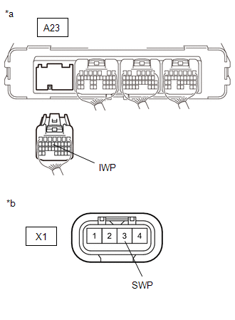
(a) Disconnect the A23 hybrid vehicle control ECU connector.
(b) Disconnect the X1 inverter water pump assembly connector.
| (c) Measure the resistance according to the value(s) in the table below.
Standard Resistance (Check for Open): |
Tester Connection | Condition |
Specified Condition | |
A23-13 (IWP) - X1-3 (SWP) |
Power switch off |
Below 1 Ω | Standard Resistance (Check for Short): |
Tester Connection | Condition |
Specified Condition | |
A23-13 (IWP) or X1-3 (SWP) - Body ground and other terminals |
Power switch off |
10 kΩ or higher | |
 |
|
*a | Rear view of wire harness connector
(to Hybrid Vehicle Control ECU) | |
*b | Front view of wire harness connector
(to Inverter Water Pump Assembly) | | |
(d) Reconnect the X1 inverter water pump assembly connector.
(e) Reconnect the A23 hybrid vehicle control ECU connector.
| NG |
| REPAIR OR REPLACE HARNESS OR CONNECTOR |
|
OK | |
| |
| 12. |
READ VALUE USING TECHSTREAM (INVERTER WATER PUMP REVOLUTION) |
NOTICE:
Be sure to perform the inspection with the auxiliary battery voltage at 11 V or more.
HINT:
When the auxiliary battery voltage is low, the inverter water pump assembly may not operate.
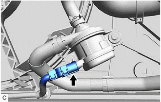
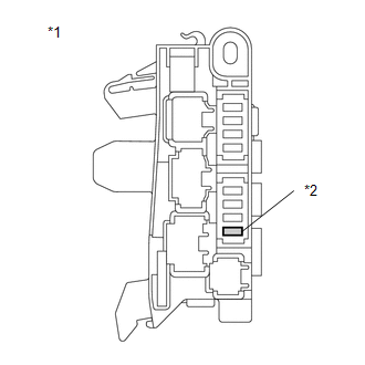
(a) Connect the Techstream to the DLC3.
| (b) Remove the INV W/PMP fuse from the No. 4 relay block. |
 |
|
*1 | No. 4 Relay Block | |
*2 | INV W/PMP Fuse | | |
(c) Turn the power switch on (IG).
(d) Enter the following menus: Powertrain / Hybrid Control / Data List / Inverter Water Pump Revolution.
Powertrain > Hybrid Control > Data List
|
Tester Display |
| Inverter Water Pump Revolution |
(e) According to the display on the Techstream, read the Data List.
Standard:
|
Techstream Display | Condition |
Specified Condition |
|
Inverter Water Pump Revolution |
Power switch on (IG) |
200 rpm or less |
(f) Turn the power switch off.
(g) Install the INV W/PMP fuse.
| NG | |
REPLACE HYBRID VEHICLE CONTROL ECU |
|
OK | |
| |
| 13. |
CHECK HARNESS AND CONNECTOR (HYBRID VEHICLE CONTROL ECU - INVERTER WATER PUMP ASSEMBLY) |
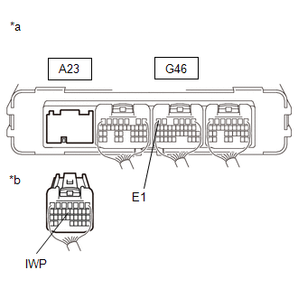
(a) Disconnect the A23 hybrid vehicle control ECU connector.
(b) Turn the power switch on (IG).
| (c) Measure the voltage according to the value(s) in the table below.
Standard Voltage: |
Tester Connection | Condition |
Specified Condition | |
A23-13 (IWP) - G46-6 (E1) |
Power switch on (IG) |
11 to 14 V | NOTICE: Turning
the power switch on (IG) with the hybrid vehicle control ECU connector
disconnected causes other DTCs to be stored. Clear the DTCs after
performing this inspection. |
 |
|
*a | Component with harness connected
(Hybrid Vehicle Control ECU) | |
*b | Rear view of wire harness connector
(to Hybrid Vehicle Control ECU) | | |
(d) Turn the power switch off.
(e) Reconnect the A23 hybrid vehicle control ECU connector.
| NG |
| GO TO STEP 15 |
|
OK | |
| |
| 14. |
CHECK HYBRID VEHICLE CONTROL ECU (CHECK WAVEFORM) |
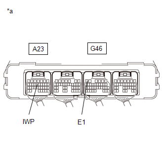
(a) Connect an oscilloscope between the hybrid vehicle control ECU terminals specified in the table below.
(b) Turn the power switch on (IG).
| (c) While turning the power switch on (IG), check the waveform between the hybrid vehicle control ECU terminals. |
Item | Content | |
Terminal | A23-13 (IWP) - G46-6 (E1) | |
Equipment Setting |
5 V/DIV., 50 ms./DIV. | |
Condition | Power switch on (IG) |
OK: Waveform duty ratio is between 3% and 9%. |
 |
|
*a | Component with harness connected
(Hybrid Vehicle Control ECU) | | |
(d) Turn the power switch off.
| NG | |
REPLACE HYBRID VEHICLE CONTROL ECU |
|
OK | |
| |
| 15. |
REPLACE INVERTER WATER PUMP ASSEMBLY |
Click here
|
NEXT | |
| |
| 16. |
ADD HV COOLANT AND PERFORM AIR BLEEDING |
(a) After replacing the inverter water pump assembly, add HV coolant and perform air bleeding.
Click here
| NEXT |
| END |