Installation
INSTALLATION
CAUTION / NOTICE / HINT
NOTICE:
This
procedure includes the installation of small-head bolts. Refer to
Small-Head Bolts of Basic Repair Hint to identify the small-head bolts.
Click here

PROCEDURE
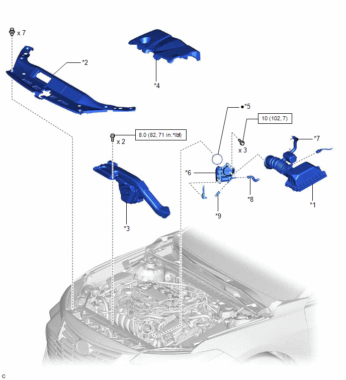
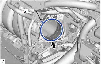
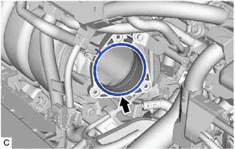
1. INSTALL THROTTLE BODY GASKET
| (a)
Install a new throttle body gasket to the intake manifold with the
protrusion of the throttle body gasket oriented as shown in the
illustration. | |
2. INSTALL THROTTLE BODY WITH MOTOR ASSEMBLY
HINT:
Perform "Inspection After Repair" after replacing the throttle body with motor assembly.
Click here
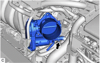
| (a) Connect the No. 6 water by-pass hose to the throttle body with motor assembly and slide the clip to secure it.
NOTICE:
- If the throttle body with motor assembly has been struck or dropped, replace it.
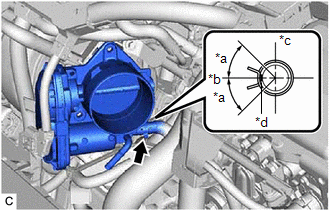
- Make sure to position the clip as shown in the illustration.
|
 |
|
*a | 45°(Claw of Clip Location) | |
*b | Left of Vehicle | |
*c | Top | |
*d | Paint Mark | | |
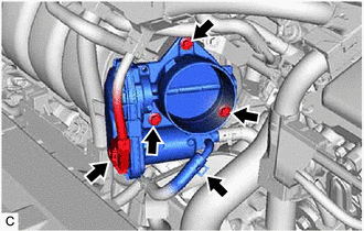
| (b) Using an 8 mm socket wrench, install the throttle body with motor assembly to the intake manifold with the 3 bolts.
Torque: 10 N·m {102 kgf·cm, 7 ft·lbf} |
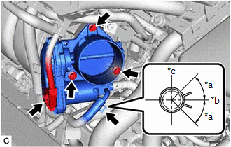 |
|
*a | 45°(Claw of Clip Location) | |
*b | Down | |
*c | Right of Vehicle | | |
(c) Connect the No. 5 water by-pass hose to the throttle body with motor assembly and slide the clip to secure it.
NOTICE:
Make sure to position the clip as shown in the illustration.
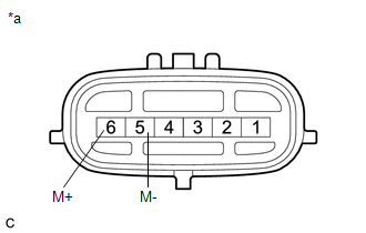
(d) Connect the throttle body with motor assembly connector.
3. INSTALL AIR CLEANER CAP WITH AIR CLEANER HOSE
| (a) Install the air cleaner cap with air cleaner hose to the throttle body with motor assembly.
NOTICE: Align the cutout of the air cleaner hose assembly with the protrusion of the throttle body with motor assembly. |
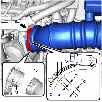 |
|
*a | Protrusion | |
*b | Cutout | |
*c | Hose Clamp End | |
*d | Paint Mark | |
*e | 2 mm (0.0787 in.) | |
*f | 4 mm (0.157 in.) | |
*g | End of Hose Clamp Location | | |
(b) Tighten the hose clamp in the position shown in the illustration.
NOTICE:
Make sure that the end of the hose clamp is positioned as shown in the illustration.
(c) Engage the 2 guides to install the air cleaner cap sub-assembly to the air cleaner case sub-assembly.
(d) Engage the 2 air cleaner cap clamps.
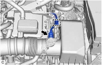
| (e) Connect the No. 2 ventilation hose to the cylinder head cover sub-assembly and slide the clip to secure it.
NOTICE: Make sure to position the clip as shown in the illustration. |
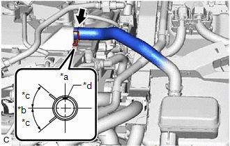 |
|
*a | Top | |
*b | Front of Vehicle | |
*c | 45°(Claw of Clip Location) | |
*d | Paint Mark | | |
(f) Engage the wire harness clamp.
(g) Connect the mass air flow meter sub-assembly connector.
4. INSTALL INLET AIR CLEANER ASSEMBLY
Click here
5. INSTALL COOL AIR INTAKE DUCT SEAL
Click here
6. INSTALL NO. 1 ENGINE COVER SUB-ASSEMBLY
Click here
7. ADD ENGINE COOLANT (for Engine)
Click here
8. INSPECT FOR COOLANT LEAK (for Engine)
Click here
9. PERFORM INITIALIZATION
NOTICE:
- Be sure to perform this procedure after removing and reinstalling the
throttle body with motor assembly or any throttle body with motor
assembly components.
- Perform the following procedure after replacing the throttle body with
motor assembly or any throttle body with motor assembly components. The
following procedure should also be performed if the throttle body with
motor assembly is cleaned.
(a) Connect the Techstream to the DLC3.
(b) Turn the power switch on (IG).
(c) Turn the Techstream on.
(d) Clear the DTCs.
Powertrain > Engine > Clear DTCs
(e) Perform "Inspection After Repair".
Click here
(f) Put the engine in Inspection Mode (Maintenance Mode).
Powertrain > Hybrid Control > Utility
|
Tester Display |
| Inspection Mode |
(g)
Start the engine and check that the MIL is not illuminated. After the
engine is warmed up, check that the idle speed is within the specified
range with the A/C switch off.
Standard Idle Speed:
1050 to 1150 rpm
NOTICE:
- Be sure to perform this step with all accessories off.
- Make sure that the shift lever is in P.
(h) Perform a road test and confirm that there are no abnormalities.
On-vehicle Inspection
ON-VEHICLE INSPECTION
PROCEDURE
1. INSPECT THROTTLE BODY WITH MOTOR ASSEMBLY
(a) Connect the Techstream to the DLC3.
(b) Turn the power switch on (IG).
(c) Turn the Techstream on.
(d) Put the engine in Inspection Mode (Maintenance Mode).
Powertrain > Hybrid Control > Utility
|
Tester Display |
| Inspection Mode |
(e)
Start the engine and check that the MIL is not illuminated. After the
engine is warmed up, check that the idle speed is within the specified
range with the A/C switch off.
Standard Idle Speed:
1050 to 1150 rpm
NOTICE:
- Be sure to perform this step with all accessories off.
- Make sure that the shift lever is in P.
(f) Perform a road test and confirm that there are no abnormalities.
Removal
REMOVAL
CAUTION / NOTICE / HINT
The
necessary procedures (adjustment, calibration, initialization, or
registration) that must be performed after parts are removed and
installed, or replaced during throttle body with motor assembly
removal/installation are shown below.
Necessary Procedures After Parts Removed/Installed/Replaced |
Replaced Part or Performed Procedure |
Necessary Procedure | Effect/Inoperative Function when Necessary Procedure not Performed |
Link |
- Replacement of throttle body with motor assembly
- Cleaning the deposits from the throttle body with motor assembly
| Inspection after repair |
- Poor idle, etc.
- Engine start function, etc.
|
 |
NOTICE:
This
procedure includes the removal of small-head bolts. Refer to Small-Head
Bolts of Basic Repair Hint to identify the small-head bolts.
Click here
PROCEDURE
1. DRAIN ENGINE COOLANT (for Engine)
Click here
2. REMOVE NO. 1 ENGINE COVER SUB-ASSEMBLY
Click here
3. REMOVE COOL AIR INTAKE DUCT SEAL
Click here
4. REMOVE INLET AIR CLEANER ASSEMBLY
Click here
5. REMOVE AIR CLEANER CAP WITH AIR CLEANER HOSE
| (a) Disconnect the mass air flow meter sub-assembly connector. |
|
(b) Disengage the wire harness clamp.
| (c) Slide the clip and disconnect the No. 2 ventilation hose from the cylinder head cover sub-assembly. |
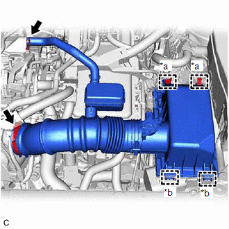 |
|
*a | Air Cleaner Cap Clamp | |
*b | Guide | | |
(d) Disengage the 2 air cleaner cap clamps.
(e) Disengage the 2 guides to separate the air cleaner cap sub-assembly from the air cleaner case sub-assembly.
(f) Loosen the hose clamp and remove the air cleaner cap with air cleaner hose from the throttle body with motor assembly.
6. REMOVE THROTTLE BODY WITH MOTOR ASSEMBLY
| (a) Disconnect the throttle body with motor assembly connector. |
|
(b) Slide the clip and disconnect the No. 5 water by-pass hose from the throttle body with motor assembly.
(c) Using an 8 mm socket wrench, remove the 3 bolts and separate the throttle body with motor assembly from the intake manifold.
| (d) Slide the clip and disconnect the No. 6 water by-pass hose to remove the throttle body with motor assembly.
NOTICE: If the throttle body with motor assembly has been struck or dropped, replace it. |
|
7. REMOVE THROTTLE BODY GASKET
| (a) Remove the throttle body gasket from the intake manifold. |
|