Components
COMPONENTS
ILLUSTRATION
|
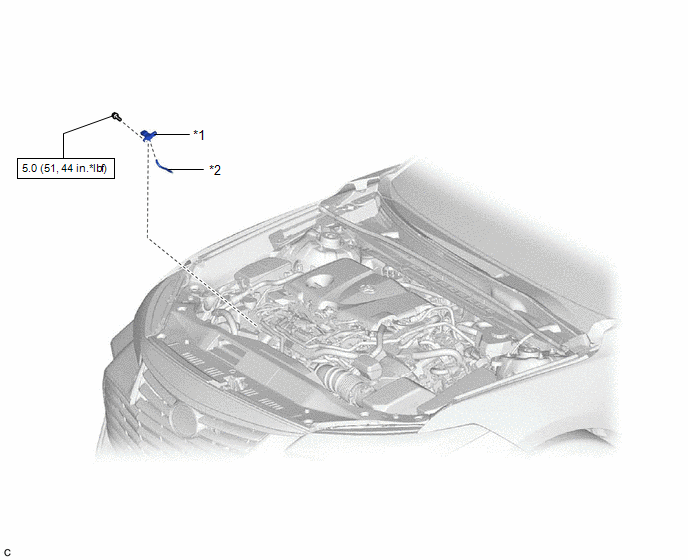
*1 | E.F.I. VACUUM SENSOR ASSEMBLY (MANIFOLD ABSOLUTE PRESSURE SENSOR) |
*2 | VACUUM HOSE |
 |
N*m (kgf*cm, ft.*lbf): Specified torque |
- | - |
Installation
INSTALLATION
CAUTION / NOTICE / HINT
NOTICE:
This procedure includes the installation of small-head bolts. Refer to Small-Head Bolts of Basic Repair Hint to identify the small-head bolts.
Click here

PROCEDURE
1. INSTALL E.F.I. VACUUM SENSOR ASSEMBLY (MANIFOLD ABSOLUTE PRESSURE SENSOR)
(a) Using an 8 mm socket wrench, install the E.F.I. vacuum sensor assembly (manifold absolute pressure sensor) to the intake manifold with the bolt.
Torque:
5.0 N·m {51 kgf·cm, 44 in·lbf}
(b) Connect the vacuum hose to the E.F.I. vacuum sensor assembly (manifold absolute pressure sensor).
(c) Connect the E.F.I. vacuum sensor assembly (manifold absolute pressure sensor) connector.
Removal
REMOVAL
CAUTION / NOTICE / HINT
NOTICE:
This procedure includes the removal of small-head bolts. Refer to Small-Head Bolts of Basic Repair Hint to identify the small-head bolts.
Click here

PROCEDURE
1. REMOVE E.F.I. VACUUM SENSOR ASSEMBLY (MANIFOLD ABSOLUTE PRESSURE SENSOR)
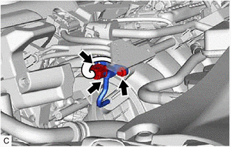
| (a) Disconnect the E.F.I. vacuum sensor assembly (manifold absolute pressure sensor) connector. |
|
(b) Disconnect the vacuum hose from the E.F.I. vacuum sensor assembly (manifold absolute pressure sensor).
(c) Using an 8 mm socket wrench, remove the bolt and E.F.I. vacuum sensor assembly (manifold absolute pressure sensor) from the intake manifold.
Toyota Avalon (XX50) 2019-2022 Service & Repair Manual > Supplemental Restraint Systems: Seat Position Sensor
Components COMPONENTS ILLUSTRATION *A w/ Seat Position Memory System - - *1 POSITION CONTROL ECU ASSEMBLY *2 SEAT POSITION AIRBAG SENSOR *3 SEAT SLIDE POSITION SENSOR PROTECTOR - - N*m (kgf*cm, ft.*lbf): Specified torque - - Installation INSTALLATION PROCEDURE 1. INSTALL SEAT POSITION AIRBAG SENSOR ...