Components
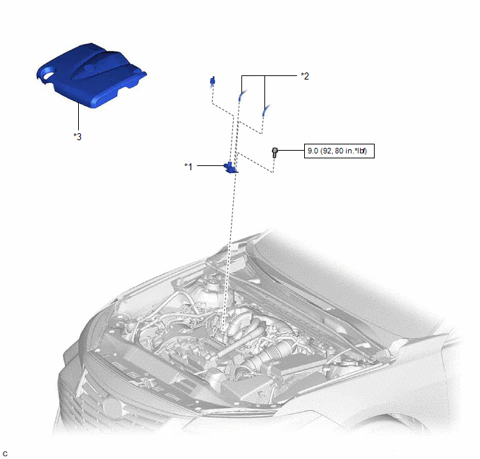
COMPONENTS
ILLUSTRATION
|
*1 | NO. 1 VACUUM SWITCHING VALVE ASSEMBLY (for ACIS) |
*2 | VACUUM HOSE SUB-ASSEMBLY |
|
*3 | V-BANK COVER SUB-ASSEMBLY |
- | - |
 |
N*m (kgf*cm, ft.*lbf): Specified torque |
- | - |
Inspection
INSPECTION
PROCEDURE
1. INSPECT NO. 1 VACUUM SWITCHING VALVE ASSEMBLY (for ACIS)
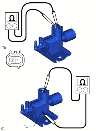
| (a) Measure the resistance according to the value(s) in the table below. Standard Resistance:
If the result is not as specified, replace the No. 1 vacuum switching valve assembly (for ACIS). |
|
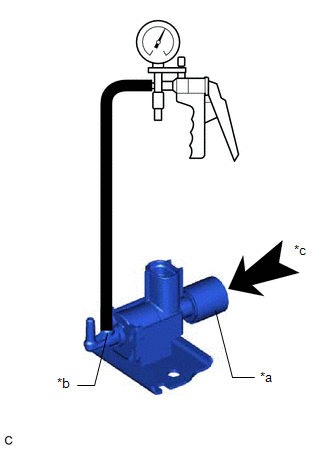
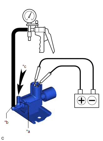
(b) Check the No. 1 vacuum switching valve assembly (for ACIS) operation.
| (1) When vacuum is applied to the port (E), check that air is sucked into the filter. If the result is not as specified, replace the No. 1 vacuum switching valve assembly (for ACIS). |
|
| (2) Apply battery voltage across the terminals. When vacuum is applied to the port (F), check that air is sucked into the port (E). If the result is not as specified, replace the No. 1 vacuum switching valve assembly (for ACIS). |
|
Installation
INSTALLATION
PROCEDURE
1. INSTALL NO. 1 VACUUM SWITCHING VALVE ASSEMBLY (for ACIS)
(a) Install the No. 1 vacuum switching valve assembly (for ACIS) to the intake air surge tank assembly with the bolt.
Torque:
9.0 N·m {92 kgf·cm, 80 in·lbf}
(b) Connect the 2 vacuum hose sub-assemblies to the No. 1 vacuum switching valve assembly (for ACIS).
(c) Connect the No. 1 vacuum switching valve assembly (for ACIS) connector.
2. INSTALL V-BANK COVER SUB-ASSEMBLY
Click here

Removal
REMOVAL
PROCEDURE
1. REMOVE V-BANK COVER SUB-ASSEMBLY
Click here

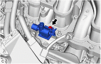
2. REMOVE NO. 1 VACUUM SWITCHING VALVE ASSEMBLY (for ACIS)
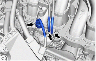
| (a) Disconnect the No. 1 vacuum switching valve assembly (for ACIS) connector. |
|
(b) Disconnect the 2 vacuum hose assemblies from the No. 1 vacuum switching valve assembly (for ACIS).
| (c) Remove the bolt and No. 1 vacuum switching valve assembly (for ACIS) from the intake air surge tank assembly. |
|
Toyota Avalon (XX50) 2019-2022 Service & Repair Manual > Maintenance: General Maintenance
Body BODY TIGHTEN BOLTS AND NUTS ON CHASSIS AND BODY (a) If necessary, tighten the bolts and nuts on the chassis parts listed below. Front axle and suspension Drivetrain Rear axle and suspension Brake system Engine mounts Other chassis parts (b) If necessary, tighten the bolts and nuts on the body p ...