Components
COMPONENTS
ILLUSTRATION
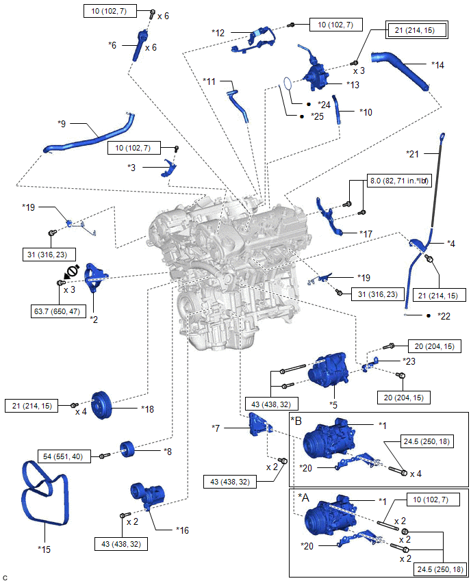
|
*A | for Type A |
*B | for Type B |
|
*1 | COMPRESSOR ASSEMBLY WITH MAGNETIC CLUTCH |
*2 | DRIVE SHAFT BEARING BRACKET |
|
*3 | ENGINE COVER BRACKET |
*4 | ENGINE OIL LEVEL DIPSTICK GUIDE |
|
*5 | GENERATOR ASSEMBLY |
*6 | IGNITION COIL ASSEMBLY |
|
*7 | NO. 1 COMPRESSOR MOUNTING BRACKET |
*8 | NO. 2 IDLER PULLEY SUB-ASSEMBLY |
|
*9 | NO. 2 VENTILATION HOSE |
*10 | NO. 2 WATER BY-PASS HOSE |
|
*11 | NO. 3 WATER BY-PASS HOSE |
*12 | SENSOR WIRE |
|
*13 | VACUUM PUMP ASSEMBLY |
*14 | VENTILATION HOSE |
|
*15 | V-RIBBED BELT |
*16 | V-RIBBED BELT TENSIONER ASSEMBLY |
|
*17 | WATER FILLER BRACKET |
*18 | WATER PUMP PULLEY |
|
*19 | WIRE HARNESS CLAMP BRACKET |
*20 | BRACKET |
|
*21 | ENGINE OIL LEVEL DIPSTICK |
*22 | ENGINE OIL LEVEL DIPSTICK GUIDE O-RING |
|
*23 | GENERATOR ASSEMBLY BRACKET |
*24 | NO. 2 O-RING |
|
*25 | NO. 3 O-RING |
- | - |
 |
Tightening torque for "Major areas involving basic vehicle performance such as moving/turning/stopping": N*m (kgf*cm, ft.*lbf) |
 |
N*m (kgf*cm, ft.*lbf): Specified torque |
|
ŌŚÅ | Non-reusable part |
 |
Do not apply lubricants to the threaded parts |
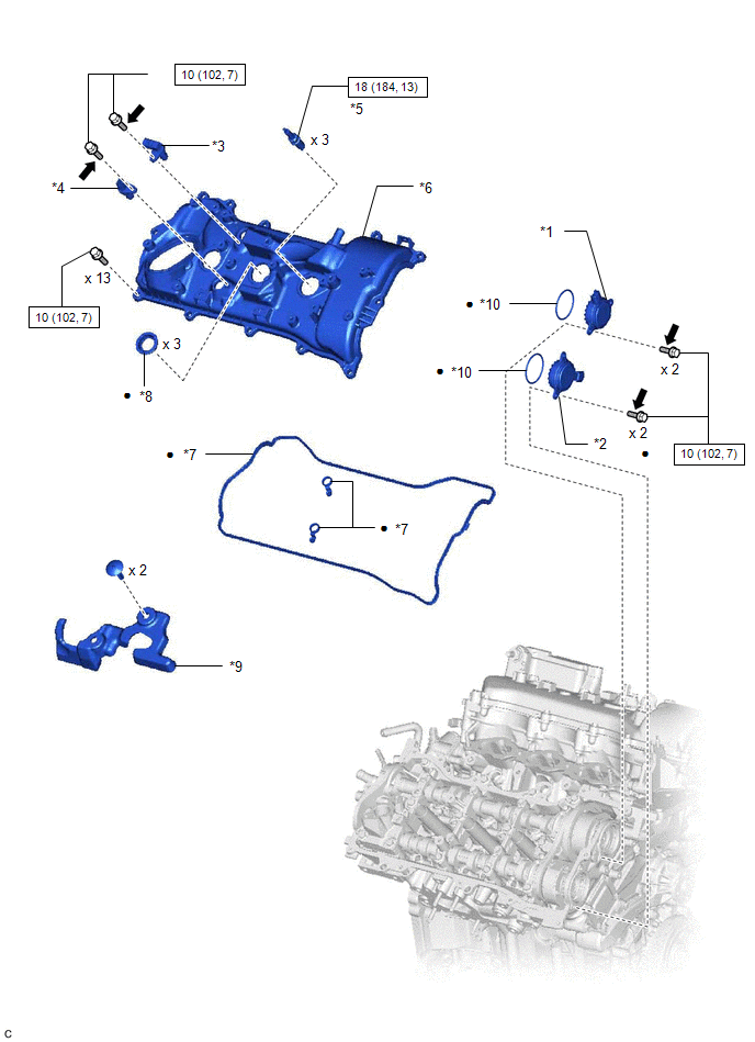
ILLUSTRATION
|
*1 | CAMSHAFT TIMING OIL CONTROL SOLENOID ASSEMBLY (for Intake Side of Bank 1) |
*2 | CAMSHAFT TIMING OIL CONTROL SOLENOID ASSEMBLY (for Exhaust Side of Bank 1) |
|
*3 | VVT SENSOR (for Intake Side of Bank 1) |
*4 | VVT SENSOR (for Exhaust Side of Bank 1) |
|
*5 | SPARK PLUG |
*6 | CYLINDER HEAD COVER SUB-ASSEMBLY |
|
*7 | CYLINDER HEAD COVER GASKET |
*8 | SPARK PLUG TUBE GASKET |
|
*9 | NO. 1 ENGINE COVER SUB-ASSEMBLY |
*10 | O-RING |
 |
N*m (kgf*cm, ft.*lbf): Specified torque |
ŌŚÅ | Non-reusable part |
 |
Adhesive 1324 | Ōśģ |
Precoated part |
ILLUSTRATION
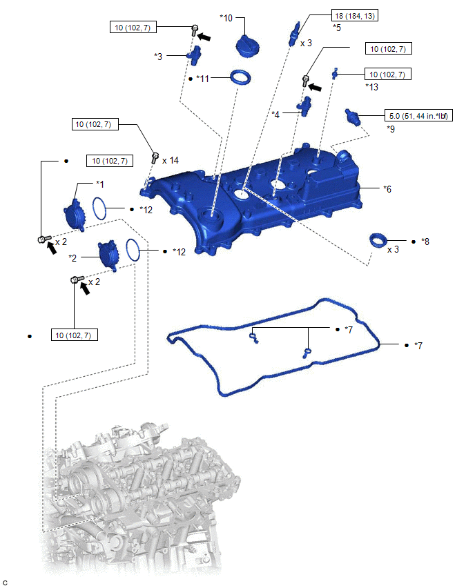
|
*1 | CAMSHAFT TIMING OIL CONTROL SOLENOID ASSEMBLY (for Intake Side of Bank 2) |
*2 | CAMSHAFT TIMING OIL CONTROL SOLENOID ASSEMBLY (for Exhaust Side of Bank 2) |
|
*3 | VVT SENSOR (for Intake Side of Bank 2) |
*4 | VVT SENSOR (for Exhaust Side of Bank 2) |
|
*5 | SPARK PLUG |
*6 | CYLINDER HEAD COVER SUB-ASSEMBLY LH |
|
*7 | NO. 2 CYLINDER HEAD COVER GASKET |
*8 | SPARK PLUG TUBE GASKET |
|
*9 | PCV VALVE (VENTILATION VALVE SUB-ASSEMBLY) |
*10 | OIL FILLER CAP SUB-ASSEMBLY |
|
*11 | OIL FILLER CAP GASKET |
*12 | O-RING |
|
*13 | NO. 1 V-BANK COVER BRACKET |
- | - |
 |
N*m (kgf*cm, ft.*lbf): Specified torque |
ŌŚÅ | Non-reusable part |
 |
Adhesive 1324 | Ōśģ |
Precoated part |
ILLUSTRATION
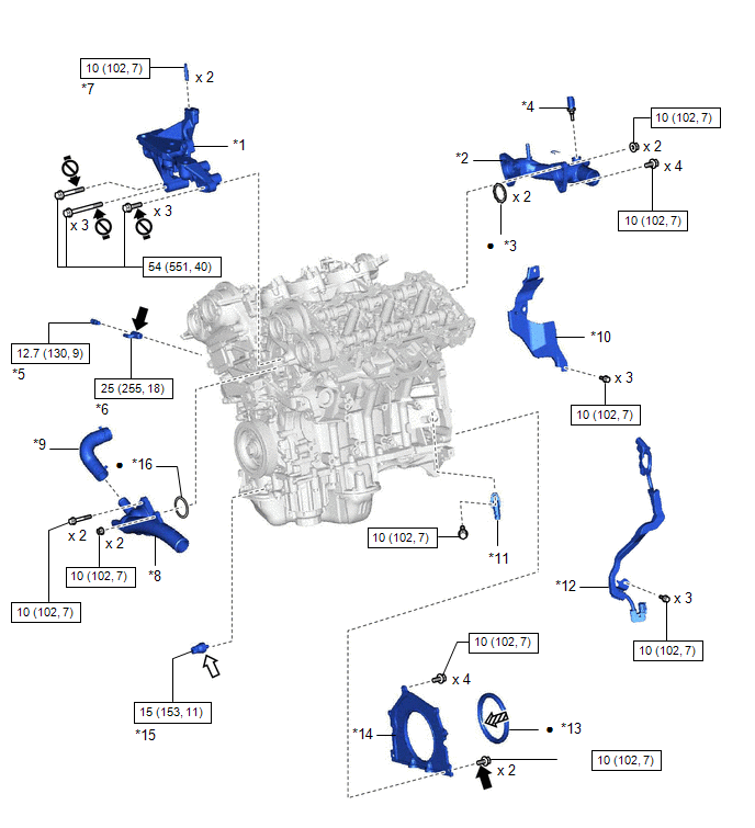
|
*1 | FRONT NO. 1 ENGINE MOUNTING BRACKET LH |
*2 | WATER OUTLET |
|
*3 | NO. 2 WATER INLET HOUSING GASKET |
*4 | ENGINE COOLANT TEMPERATURE SENSOR |
|
*5 | CYLINDER BLOCK WATER DRAIN COCK PLUG |
*6 | CYLINDER BLOCK WATER DRAIN COCK SUB-ASSEMBLY |
|
*7 | STUD BOLT |
*8 | WATER INLET WITH THERMOSTAT SUB-ASSEMBLY |
|
*9 | WATER BY-PASS HOSE |
*10 | CRANKSHAFT POSITION SENSOR PROTECTOR |
|
*11 | CRANKSHAFT POSITION SENSOR |
*12 | SENSOR WIRE |
|
*13 | REAR ENGINE OIL SEAL |
*14 | REAR ENGINE OIL SEAL RETAINER |
|
*15 | ENGINE OIL PRESSURE SWITCH ASSEMBLY |
*16 | GASKET |
 |
N*m (kgf*cm, ft.*lbf): Specified torque |
ŌŚÅ | Non-reusable part |
 |
Adhesive 1324 |
 |
Adhesive 1344 |
 |
MP grease | Ōśģ |
Precoated part |
 |
Do not apply lubricants to the threaded parts |
- | - |
ILLUSTRATION
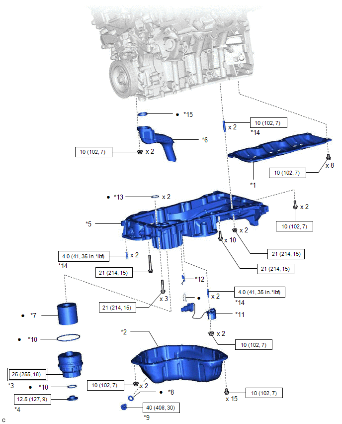
|
*1 | NO. 1 OIL PAN BAFFLE PLATE |
*2 | NO. 2 OIL PAN SUB-ASSEMBLY |
|
*3 | OIL FILTER CAP ASSEMBLY |
*4 | OIL FILTER DRAIN PLUG |
|
*5 | OIL PAN SUB-ASSEMBLY |
*6 | OIL STRAINER SUB-ASSEMBLY |
|
*7 | OIL FILTER ELEMENT |
*8 | OIL PAN DRAIN PLUG GASKET |
|
*9 | OIL PAN DRAIN PLUG |
*10 | O-RING |
|
*11 | ENGINE OIL LEVEL SENSOR |
*12 | OIL FILTER BRACKET CLIP |
|
*13 | OIL PAN GASKET |
*14 | STUD BOLT |
|
*15 | OIL STRAINER GASKET |
- | - |
 |
Tightening torque for "Major areas involving basic vehicle performance such as moving/turning/stopping": N*m (kgf*cm, ft.*lbf) |
 |
N*m (kgf*cm, ft.*lbf): Specified torque |
|
ŌŚÅ | Non-reusable part |
- | - |
ILLUSTRATION
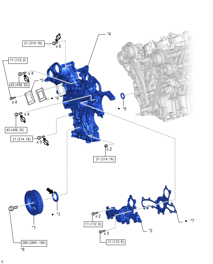
|
*1 | CRANKSHAFT PULLEY |
*2 | ENGINE WATER PUMP ASSEMBLY |
|
*3 | TIMING CHAIN CASE OIL SEAL |
*4 | TIMING CHAIN COVER ASSEMBLY |
|
*5 | TIMING CHAIN COVER PLATE |
*6 | TIMING CHAIN COVER GASKET |
|
*7 | WATER PUMP GASKET |
*8 | CRANKSHAFT PULLEY SET BOLT |
|
*9 | OIL PUMP GASKET |
- | - |
 |
N*m (kgf*cm, ft.*lbf): Specified torque |
ŌŚÅ | Non-reusable part |
 |
MP grease |
 |
Do not apply lubricants to the threaded parts |
ILLUSTRATION
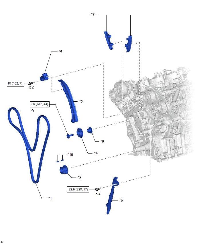
|
*1 | CHAIN SUB-ASSEMBLY |
*2 | CHAIN TENSIONER SLIPPER |
|
*3 | CRANKSHAFT TIMING SPROCKET |
*4 | IDLE SPROCKET ASSEMBLY |
|
*5 | NO. 1 CHAIN TENSIONER ASSEMBLY |
*6 | NO. 1 CHAIN VIBRATION DAMPER |
|
*7 | NO. 2 CHAIN VIBRATION DAMPER |
*8 | NO. 1 IDLE GEAR SHAFT |
|
*9 | NO. 2 IDLE GEAR SHAFT |
*10 | CRANKSHAFT TIMING GEAR KEY |
 |
N*m (kgf*cm, ft.*lbf): Specified torque |
- | - |
ILLUSTRATION
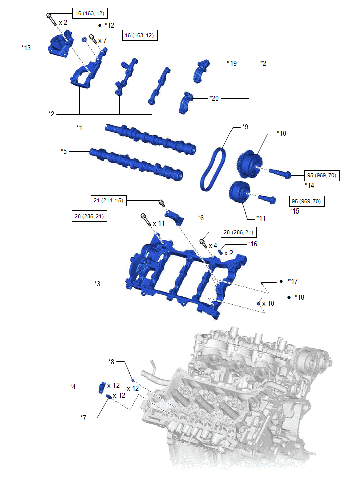
|
*1 | CAMSHAFT |
*2 | CAMSHAFT BEARING CAP (for Bank 1) |
|
*3 | CAMSHAFT HOUSING SUB-ASSEMBLY |
*4 | NO. 1 VALVE ROCKER ARM SUB-ASSEMBLY |
|
*5 | NO. 2 CAMSHAFT |
*6 | NO. 2 CHAIN TENSIONER ASSEMBLY |
|
*7 | VALVE LASH ADJUSTER ASSEMBLY |
*8 | VALVE STEM CAP |
|
*9 | NO. 2 CHAIN SUB-ASSEMBLY (for Bank 1) |
*10 | CAMSHAFT TIMING GEAR ASSEMBLY (for Bank 1) |
|
*11 | CAMSHAFT TIMING EXHAUST GEAR ASSEMBLY (for Bank 1) |
*12 | CAMSHAFT BEARING CAP OIL HOLE GASKET |
|
*13 | FUEL PUMP LIFTER HOUSING |
*14 | CAMSHAFT TIMING GEAR BOLT (for Intake Side of Bank 1) |
|
*15 | CAMSHAFT TIMING GEAR BOLT (for Exhaust Side of Bank 1) |
*16 | OIL CONTROL VALVE FILTER |
|
*17 | STRAIGHT PIN (for Bank 1) |
*18 | CAMSHAFT BEARING CAP SETTING RING PIN (for Bank 1) |
|
*19 | NO. 1 CAMSHAFT BEARING CAP |
*20 | NO. 2 CAMSHAFT BEARING CAP |
 |
N*m (kgf*cm, ft.*lbf): Specified torque |
ŌŚÅ | Non-reusable part |
ILLUSTRATION
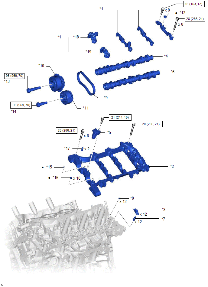
|
*1 | CAMSHAFT BEARING CAP (for Bank 2) |
*2 | CAMSHAFT HOUSING SUB-ASSEMBLY LH |
|
*3 | NO. 1 VALVE ROCKER ARM SUB-ASSEMBLY |
*4 | NO. 3 CAMSHAFT SUB-ASSEMBLY |
|
*5 | NO. 3 CHAIN TENSIONER ASSEMBLY |
*6 | NO. 4 CAMSHAFT SUB-ASSEMBLY |
|
*7 | VALVE LASH ADJUSTER ASSEMBLY |
*8 | VALVE STEM CAP |
|
*9 | NO. 2 CHAIN SUB-ASSEMBLY (for Bank 2) |
*10 | CAMSHAFT TIMING GEAR ASSEMBLY (for Bank 2) |
|
*11 | CAMSHAFT TIMING EXHAUST GEAR ASSEMBLY (for Bank 2) |
*12 | CAMSHAFT BEARING CAP OIL HOLE GASKET LH |
|
*13 | CAMSHAFT TIMING GEAR BOLT (for Intake Side of Bank 2) |
*14 | CAMSHAFT TIMING GEAR BOLT (for Exhaust Side of Bank 2) |
|
*15 | STRAIGHT PIN (for Bank 2) |
*16 | CAMSHAFT BEARING CAP SETTING RING PIN (for Bank 2) |
|
*17 | OIL CONTROL VALVE FILTER |
*18 | NO. 3 CAMSHAFT BEARING CAP |
|
*19 | NO. 4 CAMSHAFT BEARING CAP |
- | - |
 |
N*m (kgf*cm, ft.*lbf): Specified torque |
ŌŚÅ | Non-reusable part |
ILLUSTRATION
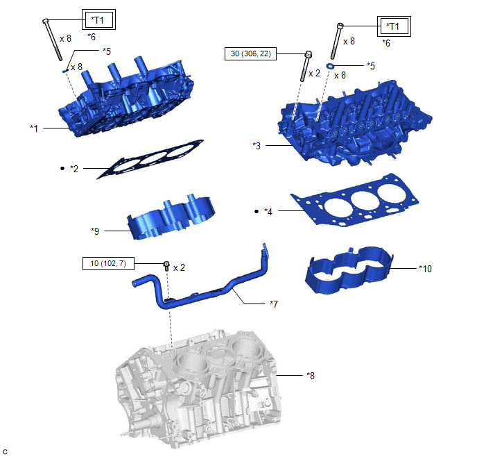
|
*1 | CYLINDER HEAD SUB-ASSEMBLY |
*2 | CYLINDER HEAD GASKET |
|
*3 | CYLINDER HEAD LH |
*4 | NO. 2 CYLINDER HEAD GASKET |
|
*5 | CYLINDER HEAD SET PLATE WASHER |
*6 | CYLINDER HEAD SET BOLT |
|
*7 | WATER INLET PIPE |
*8 | CYLINDER BLOCK SUB-ASSEMBLY |
|
*9 | CYLINDER BLOCK WATER JACKET SPACER |
*10 | CYLINDER BLOCK WATER JACKET SPACER LH |
 |
Tightening torque for "Major areas involving basic vehicle performance such as moving/turning/stopping": N*m (kgf*cm, ft.*lbf) |
 |
N*m (kgf*cm, ft.*lbf): Specified torque |
|
ŌŚÅ | Non-reusable part |
- | - |
|
*T1 | 1st: 36 (367, 27)
2nd: Turn 90┬░ 3rd: Turn 90┬░ |
- | - |
Disassembly
DISASSEMBLY
PROCEDURE
1. REMOVE OIL FILLER CAP SUB-ASSEMBLY
| (a) Remove the oil filler cap sub-assembly from the cylinder head cover sub-assembly LH. |
|
| (b) Remove the oil filler cap gasket from the oil filler cap sub-assembly. |
|
2. REMOVE SPARK PLUG
Click here 
3. REMOVE PCV VALVE (VENTILATION VALVE SUB-ASSEMBLY)
Click here

4. REMOVE CYLINDER BLOCK WATER DRAIN COCK SUB-ASSEMBLY
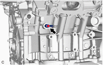
(a) Remove the cylinder block water drain cock plug from the cylinder block water drain cock sub-assembly.
(b) Remove the cylinder block water drain cock sub-assembly from the cylinder block sub-assembly.
5. REMOVE CRANKSHAFT PULLEY
Click here 
6. REMOVE FRONT NO. 1 ENGINE MOUNTING BRACKET LH
| (a) Remove the 7 bolts and front No. 1 engine mounting bracket LH from the timing chain cover assembly. |
|
7. REMOVE WATER BY-PASS HOSE
| (a) Slide the 2 clips and remove the water by-pass hose from the water inlet pipe and water inlet with thermostat sub-assembly. |
|
8. REMOVE WATER INLET WITH THERMOSTAT SUB-ASSEMBLY
Click here

9. REMOVE CAMSHAFT TIMING OIL CONTROL SOLENOID ASSEMBLY (for Intake Side of Bank 1)
Click here 
10. REMOVE CAMSHAFT TIMING OIL CONTROL SOLENOID ASSEMBLY (for Exhaust Side of Bank 1)
Click here 
11. REMOVE CAMSHAFT TIMING OIL CONTROL SOLENOID ASSEMBLY (for Exhaust Side of Bank 2)
Click here 
12. REMOVE CAMSHAFT TIMING OIL CONTROL SOLENOID ASSEMBLY (for Intake Side of Bank 2)
Click here 
13. REMOVE VVT SENSOR (for Intake Side of Bank 1)
Click here 
14. REMOVE VVT SENSOR (for Exhaust Side of Bank 1)
Click here 
15. REMOVE VVT SENSOR (for Intake Side of Bank 2)
Click here 
16. REMOVE VVT SENSOR (for Exhaust Side of Bank 2)
Click here 
17. REMOVE CRANKSHAFT POSITION SENSOR PROTECTOR
Click here 
18. REMOVE CRANKSHAFT POSITION SENSOR
Click here 
19. REMOVE ENGINE COOLANT TEMPERATURE SENSOR
Click here 
20. REMOVE WATER OUTLET
(a) Remove the 4 bolts, 2 nuts and water outlet from the cylinder head sub-assembly and cylinder head LH.
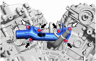
 |
Bolt |
 |
Nut |
| (b) Remove the 2 No. 2 water inlet housing gaskets from the water outlet. |
|
21. REMOVE CYLINDER HEAD COVER SUB-ASSEMBLY
| (a) Remove the 2 clips and No. 1 engine cover sub-assembly from the cylinder head cover sub-assembly. |
|
| (b) Remove the 13 bolts and cylinder head cover sub-assembly from the camshaft housing sub-assembly. |
|
| (c) Remove the camshaft bearing cap oil hole gasket from the camshaft bearing cap. |
|
| (d) Remove the 3 cylinder head cover gaskets from the cylinder head cover sub-assembly. |
|
22. REMOVE CYLINDER HEAD COVER SUB-ASSEMBLY LH
| (a) Remove the No. 1 V-bank cover bracket from the cylinder head cover sub-assembly LH. |
|
| (b) Remove the 14 bolts and cylinder head cover sub-assembly LH from the camshaft housing sub-assembly LH. |
|
| (c) Remove the camshaft bearing cap oil hole gasket LH from the camshaft bearing cap. |
|
| (d) Remove the 3 No. 2 cylinder head cover gaskets from the cylinder head cover sub-assembly LH. |
|
23. REMOVE SPARK PLUG TUBE GASKET
| (a)
Using a screwdriver as shown in the illustration, deform each spark
plug tube gasket inwards and remove the 6 spark plug tube gaskets from
the cylinder head cover sub-assembly and cylinder head cover
sub-assembly LH. | |
24. REMOVE OIL PAN DRAIN PLUG
| (a) Remove the oil pan drain plug and oil pan drain plug gasket from the No. 2 oil pan sub-assembly. |
|
25. REMOVE OIL FILTER CAP ASSEMBLY
Click here

26. REMOVE ENGINE OIL PRESSURE SWITCH ASSEMBLY
Click here 
27. REMOVE NO. 2 OIL PAN SUB-ASSEMBLY
| (a) Remove the 15 bolts and 2 nuts from the No. 2 oil pan sub-assembly. |
|
| (b)
Insert the blade of an oil pan seal cutter between the oil pan
sub-assembly and No. 2 oil pan sub-assembly. Cut through the applied
sealer and remove the No. 2 oil pan sub-assembly. NOTICE: Be careful not to damage the contact surfaces of the oil pans. |
|
28. REMOVE OIL STRAINER SUB-ASSEMBLY
| (a) Remove the 2 nuts and oil strainer sub-assembly from the timing chain cover assembly. |
|
| (b) Remove the oil strainer gasket from the oil strainer sub-assembly. |
|
29. REMOVE ENGINE OIL LEVEL SENSOR
Click here

30. REMOVE OIL PAN SUB-ASSEMBLY
Click here

31. REMOVE OIL FILTER BRACKET CLIP
| (a) Remove the oil filter bracket clip from the oil pan sub-assembly. |
|
32. REMOVE NO. 1 OIL PAN BAFFLE PLATE
| (a) Remove the 8 bolts and No. 1 oil pan baffle plate from the crankshaft bearing cap set bolt. |
|
33. REMOVE TIMING CHAIN COVER PLATE
| (a) Remove the 4 bolts, timing chain cover plate and timing chain cover gasket from the timing chain cover assembly. |
|
34. REMOVE TIMING CHAIN CASE OIL SEAL
Click here

35. REMOVE TIMING CHAIN COVER ASSEMBLY
Click here 
36. REMOVE ENGINE WATER PUMP ASSEMBLY
| (a) Remove the 7 bolts, engine water pump assembly and water pump gasket from the timing chain cover assembly. |
|
37. SET NO. 1 CYLINDER TO TDC (COMPRESSION)
(a) Temporarily tighten the crankshaft pulley set bolt to the crankshaft.
| (b)
Turn the crankshaft clockwise to align the timing mark of the
crankshaft timing sprocket key groove chase position with the center
line of the block bore (for Bank 1) (TDC / compression). |
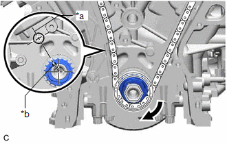 |
|
*a | Center Line | |
*b | Key Groove | | |
(c)
Check that the timing marks of the camshaft timing gear assembly and
camshaft timing exhaust gear assembly are aligned with the timing marks
of the camshaft bearing caps as shown in the illustration.
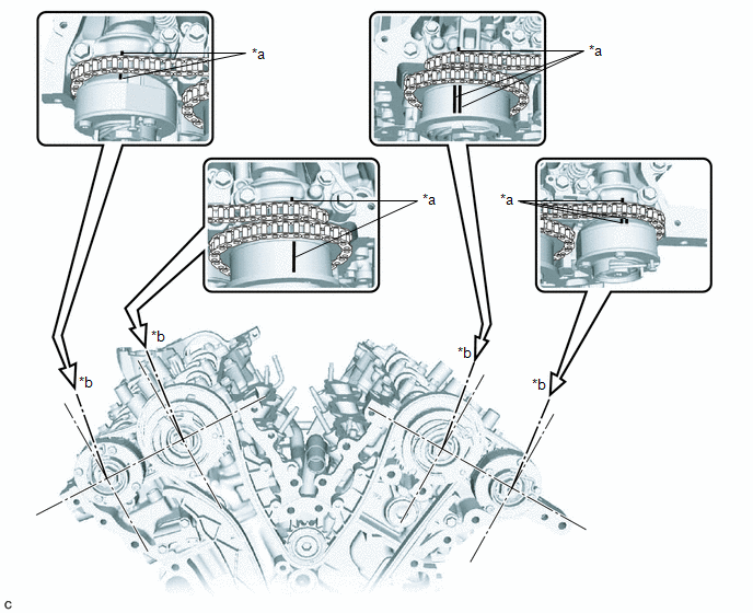
|
*a | Timing Mark |
*b | Viewpoint |
NOTICE:
- Check each timing mark from a viewpoint directly in line with the center
of the camshaft and the timing mark on each camshaft timing gear
assembly and each camshaft timing exhaust gear assembly.
- If the timing marks are checked from any other viewpoint, the valve timing may appear misaligned.
HINT:
38. REMOVE NO. 1 CHAIN TENSIONER ASSEMBLY
| (a) Turn the stopper plate clockwise to release the lock, and push the plunger deep into the No. 1 chain tensioner assembly. |
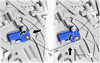 |
|
*a | Plunger | |
*b | Stopper Plate | |
*c | Pin | | |
(b)
Turn the stopper plate counterclockwise to set the lock, and insert a
1.0 mm (0.0394 in.) diameter pin into the hole of the stopper plate.
| (c) Remove the 2 bolts and No. 1 chain tensioner assembly from the cylinder head sub-assembly. |
|
39. REMOVE CHAIN TENSIONER SLIPPER
| (a) Remove the chain tensioner slipper from the cylinder block sub-assembly. |
|
40. REMOVE CHAIN SUB-ASSEMBLY
| (a) Turn the crankshaft 10┬░ counterclockwise to loosen the chain sub-assembly of the crankshaft timing sprocket. |
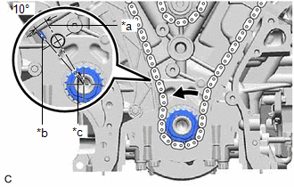 |
|
*a | Center Line | |
*b | Mark | |
*c | Key Groove | | |
(b) Remove the crankshaft pulley set bolt from the crankshaft.
| (c) Remove the chain sub-assembly from the crankshaft timing sprocket and place it on the crankshaft. |
|
| (d)
Turn the camshaft timing gear assembly on bank 1 clockwise
(approximately 60┬░) so that it is positioned as shown in the
illustration. NOTICE: Be sure to loosen the chain sub-assembly between the banks. |
|
(e) Remove the chain sub-assembly from the engine assembly.
41. REMOVE IDLE SPROCKET ASSEMBLY
| (a)
Using a 10 mm hexagon socket wrench, remove the No. 2 idle gear shaft,
idle sprocket assembly and No. 1 idle gear shaft from the cylinder block
sub-assembly. | |
42. REMOVE NO. 1 CHAIN VIBRATION DAMPER
| (a) Remove the 2 bolts and No. 1 chain vibration damper from the cylinder head LH and cylinder block sub-assembly. |
|
43. REMOVE NO. 2 CHAIN VIBRATION DAMPER
| (a) Remove the 2 No. 2 chain vibration dampers from the cylinder head LH and cylinder head sub-assembly. |
|
44. REMOVE CRANKSHAFT TIMING SPROCKET
| (a) Remove the crankshaft timing sprocket from the crankshaft. |
|
45. REMOVE CRANKSHAFT TIMING GEAR KEY
| (a) Remove the 2 crankshaft timing gear keys from the crankshaft. |
|
46. REMOVE CAMSHAFT TIMING GEAR ASSEMBLY, CAMSHAFT TIMING EXHAUST GEAR ASSEMBLY AND NO. 2 CHAIN SUB-ASSEMBLY (for Bank 1)
(a)
While raising the No. 2 chain tensioner assembly, insert a 1.0 mm
(0.0394 in.) diameter pin into the hole to secure the No. 2 chain
tensioner assembly.
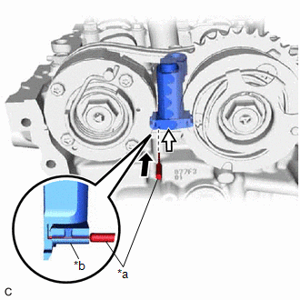
|
*a | Pin |
|
*b | Plunger |
 |
Push |
(b)
Using a wrench to hold the hexagonal portion of camshaft, loosen the
camshaft timing gear bolt of the camshaft timing gear assembly.
NOTICE:
- Be careful not to damage the camshaft, camshaft housing sub-assembly or spark plug tube with wrench.
- Do not loosen any other bolt. If any other bolt is loosened, replace the
camshaft timing gear assembly and/or the camshaft timing exhaust gear
assembly with a new one.
- If the camshaft timing gear bolt has been struck or dropped, replace it.
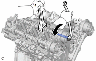
|
*a | Hold |
 |
Turn |
(c)
Using a wrench to hold the hexagonal portion of No. 2 camshaft, loosen
the camshaft timing gear bolt of the camshaft timing exhaust gear
assembly.
NOTICE:
- Be careful not to damage the No. 2 camshaft, camshaft housing sub-assembly or spark plug tube with wrench.
- Do not loosen any other bolt. If any other bolt is loosened, replace the
camshaft timing gear assembly and/or the camshaft timing exhaust gear
assembly with a new one.
- If the camshaft timing gear bolt has been struck or dropped, replace it.
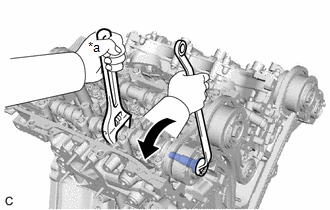
|
*a | Hold |
 |
Turn |
(d)
Remove the 2 camshaft timing gear bolts, camshaft timing gear assembly
and camshaft timing exhaust gear assembly together with the No. 2 chain
sub-assembly.
47. REMOVE NO. 2 CHAIN TENSIONER ASSEMBLY
| (a) Remove the bolt and No. 2 chain tensioner assembly from the camshaft housing sub-assembly. |
|
48. REMOVE CAMSHAFT BEARING CAP (for Bank 1)
| (a) Check that the camshaft and No. 2 camshaft are positioned as shown in the illustration. |
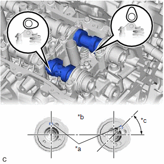 |
|
*a | Straight Pin | |
*b | Front View | |
*c | 45┬░ | | |
| (b) Uniformly loosen and remove the 9 bolts in several steps in the order shown in the illustration. |
|
| (c) Uniformly loosen and remove the 15 bolts in several steps in the order shown in the illustration.
NOTICE: Make sure that the camshaft and No. 2 camshaft remain level while uniformly loosening the bolts. |
|
| (d) Remove the fuel pump lifter housing from the camshaft housing sub-assembly. |
|
| (e) Remove the 5 camshaft bearing caps from the camshaft housing sub-assembly. |
|
| (f) Remove the 2 oil control valve filters from the 2 camshaft bearing caps. |
|
49. REMOVE CAMSHAFT
(a) Remove the camshaft from the camshaft housing sub-assembly.
50. REMOVE NO. 2 CAMSHAFT
(a) Remove the No. 2 camshaft from the camshaft housing sub-assembly.
51. REMOVE CAMSHAFT HOUSING SUB-ASSEMBLY
| (a)
Remove the camshaft housing sub-assembly by prying between the cylinder
head sub-assembly and camshaft housing sub-assembly with a screwdriver
with its tip wrapped with protective tape. NOTICE: Be careful not to damage the contact surfaces of the cylinder head sub-assembly and camshaft housing sub-assembly. |
|
52. REMOVE CAMSHAFT TIMING GEAR ASSEMBLY, CAMSHAFT TIMING EXHAUST GEAR ASSEMBLY AND NO. 2 CHAIN SUB-ASSEMBLY (for Bank 2)
(a)
While pushing down the No. 3 chain tensioner assembly, insert a 1.0 mm
(0.0394 in.) diameter pin into the hole to secure the No. 3 chain
tensioner assembly.
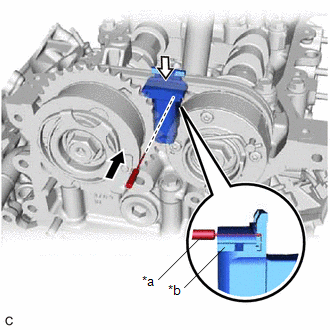
|
*a | Pin |
|
*b | Plunger |
 |
Push |
(b)
Using a wrench to hold the hexagonal portion of No. 3 camshaft
sub-assembly, loosen the camshaft timing gear bolt of the camshaft
timing gear assembly.
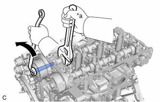
|
*a | Hold |
 |
Turn |
NOTICE:
- Be careful not to damage the No. 3 camshaft sub-assembly, camshaft housing sub-assembly LH or spark plug tube with wrench.
- Do not loosen any other bolt. If any other bolt is loosened, replace the
camshaft timing gear assembly and/or the camshaft timing exhaust gear
assembly with a new one.
- If the camshaft timing gear bolt has been struck or dropped, replace it.
(c) Using a wrench to hold the
hexagonal portion of No. 4 camshaft sub-assembly, loosen the camshaft
timing gear bolt of the camshaft timing exhaust gear assembly.
NOTICE:
- Be careful not to damage the No. 4 camshaft sub-assembly, camshaft housing sub-assembly LH or spark plug tube with wrench.
- Do not loosen any other bolt. If any other bolt is loosened, replace the
camshaft timing gear assembly and/or the camshaft timing exhaust gear
assembly with a new one.
- If the camshaft timing gear bolt has been struck or dropped, replace it.
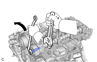
|
*a | Hold |
 |
Turn |
(d)
Remove the 2 camshaft timing gear bolts, camshaft timing gear assembly
and camshaft timing exhaust gear assembly together with the No. 2 chain
sub-assembly.
53. REMOVE NO. 3 CHAIN TENSIONER ASSEMBLY
| (a) Remove the bolt and No. 3 chain tensioner assembly from the camshaft housing sub-assembly LH. |
|
54. REMOVE CAMSHAFT BEARING CAP (for Bank 2)
| (a) Check that the No. 3 camshaft sub-assembly and No. 4 camshaft sub-assembly are positioned as shown in the illustration. |
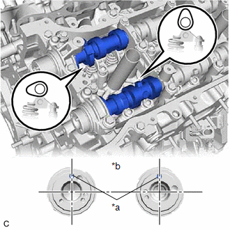 |
|
*a | Straight Pin | |
*b | Front View | | |
| (b) Uniformly loosen and remove the 8 bolts in several steps in the order shown in the illustration. |
|
| (c) Uniformly loosen and remove the 15 bolts in several steps in the order shown in the illustration.
NOTICE: Make sure that the No. 3 camshaft sub-assembly and No. 4 camshaft sub-assembly remain level while uniformly loosening the bolts. |
|
| (d) Remove the 5 camshaft bearing caps from the camshaft housing sub-assembly LH. |
|
| (e) Remove the 2 oil control valve filters from the 2 camshaft bearing caps. |
|
55. REMOVE NO. 3 CAMSHAFT SUB-ASSEMBLY
(a) Remove the No. 3 camshaft sub-assembly from the camshaft housing sub-assembly LH.
56. REMOVE NO. 4 CAMSHAFT SUB-ASSEMBLY
(a) Remove the No. 4 camshaft sub-assembly from the camshaft housing sub-assembly LH.
57. REMOVE CAMSHAFT HOUSING SUB-ASSEMBLY LH
| (a)
Remove the camshaft housing sub-assembly LH by prying between the
cylinder head LH and camshaft housing sub-assembly LH with a screwdriver
with its tip wrapped with protective tape. NOTICE: Be careful not to damage the contact surfaces of the cylinder head LH and camshaft housing sub-assembly LH. |
|
58. REMOVE NO. 1 VALVE ROCKER ARM SUB-ASSEMBLY
| (a) Remove the 24 No. 1 valve rocker arm sub-assemblies from the cylinder head sub-assembly and cylinder head LH.
HINT: Arrange the removed parts in such a way that they can be reinstalled to their original locations. |
|
59. REMOVE VALVE LASH ADJUSTER ASSEMBLY
| (a) Remove the 24 valve lash adjuster assemblies from the cylinder head sub-assembly and cylinder head LH.
HINT: Arrange the removed parts in such a way that they can be reinstalled to their original locations. |
|
60. REMOVE VALVE STEM CAP
| (a) Remove the 24 valve stem caps from the cylinder head sub-assembly and cylinder head LH.
HINT: Arrange the removed parts in such a way that they can be reinstalled to their original locations. |
|
61. REMOVE SENSOR WIRE
|
(a) Remove the 3 bolts and sensor wire from the cylinder head LH and cylinder block sub-assembly. |
|
62. REMOVE REAR ENGINE OIL SEAL RETAINER
| (a) Remove the 6 bolts from the rear engine oil seal retainer. |
|
(b) Using a screwdriver with its tip wrapped with protective tape, pry out the rear engine oil seal retainer.
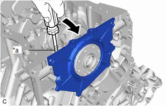
|
*a | Protective Tape |
 |
Pry |
NOTICE:
Be careful not to damage the rear engine oil seal retainer.
63. REMOVE REAR ENGINE OIL SEAL
| (a) Place the rear engine oil seal retainer on wooden blocks. |
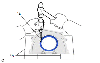 |
|
*a | Protective Tape | |
*b | Wooden Block | | |
(b) Using a hammer and a screwdriver with its tip wrapped with protective tape, tap out the rear engine oil seal.
NOTICE:
Be careful not to damage the rear engine oil seal retainer.
64. REMOVE CYLINDER HEAD SUB-ASSEMBLY
| (a)
Using a 10 mm bi-hexagon socket wrench, uniformly loosen the 8 cylinder
head set bolts in the order shown in the illustration. Remove the 8
cylinder head set bolts and 8 cylinder head set plate washers.
NOTICE:
- Be careful not to drop the cylinder head set plate washers into the cylinder head sub-assembly.
- Warpage or cracking of the cylinder head sub-assembly may result from
removing the cylinder head set bolts in the incorrect order.
HINT: Arrange the removed parts in such a way that they can be reinstalled to their original locations. |
|
(b) Remove the cylinder head sub-assembly from the cylinder block sub-assembly.
65. REMOVE CYLINDER HEAD GASKET
Click here

66. REMOVE CYLINDER HEAD LH
| (a) Uniformly loosen and remove the 2 bolts in several steps in the order shown in the illustration. |
|
| (b)
Using a 10 mm bi-hexagon socket wrench, uniformly loosen the 8 cylinder
head set bolts in the order shown in the illustration. Remove the 8
cylinder head set bolts and 8 cylinder head set plate washers.
NOTICE:
- Be careful not to drop the cylinder head set plate washers into the cylinder head LH.
- Warpage or cracking of the cylinder head LH may result from removing the cylinder head set bolts in the incorrect order.
HINT: Arrange the removed parts in such a way that they can be reinstalled to their original locations. |
|
(c) Remove the cylinder head LH from the cylinder block sub-assembly.
67. REMOVE NO. 2 CYLINDER HEAD GASKET
Click here 
68. REMOVE WATER INLET PIPE
| (a) Remove the 2 bolts and water inlet pipe from the cylinder block sub-assembly. |
|
69. REMOVE CYLINDER BLOCK WATER JACKET SPACER
| (a)
Remove the cylinder block water jacket spacer and cylinder block water
jacket spacer LH from the cylinder block sub-assembly. | |
70. REMOVE STRAIGHT PIN
NOTICE:
It is not necessary to remove the straight pins unless they are being replaced.
71. REMOVE CAMSHAFT BEARING CAP SETTING RING PIN
NOTICE:
It is not necessary to remove the camshaft bearing cap setting ring pins unless they are being replaced.
72. REMOVE STUD BOLT
NOTICE:
If a stud bolt is deformed or its threads are damaged, replace it.
Inspection
INSPECTION
PROCEDURE
1. INSPECT NO. 1 VALVE ROCKER ARM SUB-ASSEMBLY
| (a) Turn the roller by hand to check that it turns smoothly. HINT:
If the roller does not turn smoothly, replace the No. 1 valve rocker arm sub-assembly. |
|
2. INSPECT VALVE LASH ADJUSTER ASSEMBLY
NOTICE:
- Keep the valve lash adjuster assembly free from dirt and foreign matter.
- Only use clean engine oil.
(a) Place the valve lash adjuster assembly into a container filled with engine oil.
| (b) Insert the tip of SST into the plunger and use the tip to press down on the check ball inside the plunger.
SST: 09276-75010 |
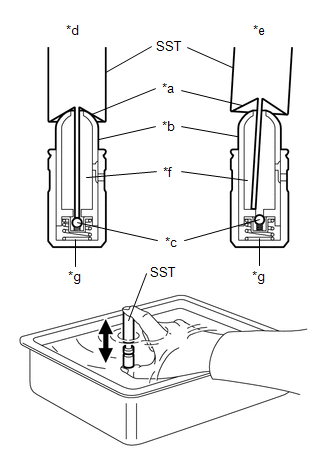 |
|
*a | Tapered Path | |
*b | Plunger | |
*c | Check Ball | |
*d | Correct | |
*e | Incorrect | |
*f | Low Pressure Chamber | |
*g | High Pressure Chamber | | |
(c) Squeeze SST and the valve lash adjuster assembly together to move the plunger up and down 5 to 6 times.
(d) Check the movement of the plunger and bleed any air.
OK:
Plunger moves up and down.
NOTICE:
When
bleeding the air from the high-pressure chamber, make sure that the tip
of SST is pressing the check ball as shown in the illustration. If the
check ball is not pressed, air will not bleed.
(e) After bleeding the air, remove SST. Then try to quickly and firmly press the plunger by hand.
OK:
Plunger is very difficult to move.
HINT:
If the plunger is easy to move, replace the valve lash adjuster assembly.
3. INSPECT CAMSHAFT
(a) Inspect the camshaft for runout.
(1) Place the camshaft on V-blocks.
| (2) Using a dial indicator, measure the runout at the center journal.
Maximum Runout: 0.04 mm (0.00157 in.)
HINT:
- If the runout is more than the maximum, replace the camshaft.
- Check the oil clearance after replacing the camshaft.
Click here
| |
| (b) Using a micrometer, measure the cam lobe height. Standard Cam Lobe Height: |
Item | Specified Condition | |
Intake camshaft | 44.335 to 44.435 mm (1.74547 to 1.74941 in.) | |
Exhaust camshaft |
43.866 to 43.966 mm (1.72701 to 1.73094 in.) | |
Exhaust (for Fuel Pump) |
40.554 to 40.654 mm (1.59661 to 1.60055 in.) |
Minimum Cam Lobe Height: |
Item | Specified Condition | |
Intake camshaft | 44.235 mm (1.74154 in.) | |
Exhaust camshaft |
43.766 mm (1.72307 in.) | |
Exhaust (for Fuel Pump) |
40.454 mm (1.59268 in.) | HINT:
If the cam lobe height is less than the minimum, replace the camshaft. |
|
| (c) Using a micrometer, measure the journal diameter. Standard Journal Diameter: |
Item | Specified Condition | |
No. 1 journal | 35.946 to 35.960 mm (1.41519 to 1.41575 in.) | |
No. 2, No. 3, No. 4 journals |
25.959 to 25.975 mm (1.02201 to 1.02264 in.) | |
No. 5 journal | 25.969 to 25.985 mm (1.02240 to 1.02303 in.) |
HINT: If the journal diameter is not as specified, check the oil clearance.
Click here | |
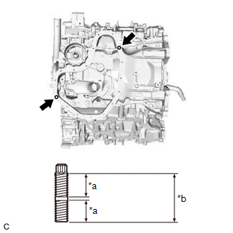
4. INSPECT CYLINDER HEAD SET BOLT
| (a) Using a vernier caliper, measure the diameter of the threads at the measurement point.
Standard Diameter: 10.85 to 11.00 mm (0.427 to 0.433 in.) Minimum Diameter:
10.70 mm (0.421 in.) Measurement Point (Distance from the Seat):
100 mm (3.94 in.)
HINT:
- If the diameter is less than the minimum, replace the cylinder head set bolt. Failure to do so may lead to engine damage.
- If there is any thread deformation, replace the cylinder head set bolt with a new one.
|
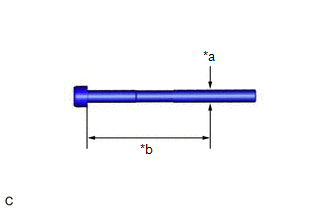 |
|
*a | Measurement Point | |
*b | 100 mm | | |
5. INSPECT CHAIN SUB-ASSEMBLY
| (a) Using a spring scale, pull the chain sub-assembly with a force of 147 N (15 kgf, 33.0 lbf) as shown in the illustration. |
|
(b) Using a vernier caliper, measure the length of 15 links.
Maximum Chain Elongation:
137.8 mm (5.43 in.)
HINT:
- Perform the measurement at 3 random places. Use the average of the measurements.
- If the average elongation is more than the maximum, replace the chain sub-assembly.
6. INSPECT NO. 2 CHAIN SUB-ASSEMBLY
| (a)
Using a spring scale, pull the No. 2 chain sub-assembly with a force of
147 N (15 kgf, 33.0 lbf) as shown in the illustration. | |
(b) Using a vernier caliper, measure the length of 15 links.
Maximum Chain Elongation:
137.8 mm (5.43 in.)
HINT:
- Perform the measurement at 3 random places. Use the average of the measurements.
- If the average elongation is more than the maximum, replace the No. 2 chain sub-assembly.
7. INSPECT CRANKSHAFT TIMING SPROCKET
(a) Place the chain sub-assembly around the crankshaft timing sprocket.
| (b) Using a vernier caliper, measure the diameter of the crankshaft timing sprocket with the chain sub-assembly.
Maximum Sprocket Diameter (with Chain Sub-assembly): 62.2 mm (2.45 in.)
HINT:
- The vernier caliper must contact the chain rollers when measuring.
- If the diameter is more than the maximum, replace the chain sub-assembly and crankshaft timing sprocket.
| |
8. INSPECT IDLE SPROCKET ASSEMBLY
(a) Place the chain sub-assembly around the idle sprocket assembly.
| (b) Using a vernier caliper, measure the diameter of the idle sprocket assembly with the chain sub-assembly.
Maximum Sprocket Diameter (with Chain Sub-assembly): 65.2 mm (2.57 in.)
HINT:
- The vernier caliper must contact the chain rollers when measuring.
- If the diameter is more than the maximum, replace the chain sub-assembly and idle sprocket assembly.
| |
9. INSPECT NO. 1 IDLE GEAR SHAFT OIL CLEARANCE
| (a) Using a micrometer, measure the diameter of the No. 1 idle gear shaft.
Standard No. 1 Idle Gear Shaft Diameter: 22.987 to 23.000 mm (0.905 to 0.906 in.) |
|
| (b) Using a caliper gauge, measure the inside diameter of the idle sprocket assembly.
Standard Idle Sprocket Assembly Inside Diameter: 23.020 to 23.030 mm (0.906 to 0.907 in.) |
|
(c) Subtract the No. 1 idle gear shaft diameter measurement from the idle sprocket assembly inside diameter measurement.
Standard Oil Clearance:
0.020 to 0.043 mm (0.000787 to 0.00169 in.)
Maximum Oil Clearance:
0.093 mm (0.00366 in.)
HINT:
If the oil clearance is more than the maximum, replace the No. 1 idle gear shaft and idle sprocket assembly.
10. INSPECT NO. 1 CHAIN TENSIONER ASSEMBLY
| (a) Turn the stopper plate clockwise to release the lock. Push the plunger and check that it moves smoothly.
HINT: If the plunger does not move smoothly, replace the No. 1 chain tensioner assembly. |
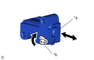 |
|
*a | Plunger | |
*b | Stopper Plate | | |
11. INSPECT NO. 2 CHAIN TENSIONER ASSEMBLY
| (a) Check that the plunger moves smoothly. | |
(b) Using a vernier caliper, measure the wear depth of the No. 2 chain tensioner assembly.
Maximum Depth:
1.0 mm (0.0394 in.)
HINT:
If the depth is more than the maximum, replace the No. 2 chain tensioner assembly.
12. INSPECT NO. 3 CHAIN TENSIONER ASSEMBLY
| (a) Check that the plunger moves smoothly. | |
(b) Using a vernier caliper, measure the wear depth of the No. 3 chain tensioner assembly.
Maximum Depth:
1.0 mm (0.0394 in.)
HINT:
If the depth is more than the maximum, replace the No. 3 chain tensioner assembly.
13. INSPECT CHAIN TENSIONER SLIPPER
| (a) Measure the wear depth of the chain tensioner slipper. Maximum Depth:
1.0 mm (0.0394 in.) HINT: If the depth is more than the maximum, replace the chain tensioner slipper. |
|
14. INSPECT NO. 1 CHAIN VIBRATION DAMPER
| (a) Using a vernier caliper, measure the wear depth of the No. 1 chain vibration damper.
Maximum Depth: 1.0 mm (0.0394 in.) HINT: If the depth is more than the maximum, replace the No. 1 chain vibration damper. |
|
15. INSPECT NO. 2 CHAIN VIBRATION DAMPER
| (a) Using a vernier caliper, measure the wear depth of the No. 2 chain vibration damper.
Maximum Depth: 1.0 mm (0.0394 in.) HINT: If the depth is more than the maximum, replace the No. 2 chain vibration damper. |
|
16. INSPECT CAMSHAFT THRUST CLEARANCE
(a) Inspect the camshaft thrust clearance (for Bank 1).
(1) Install the camshaft.
Click here 
(2) Install the No. 2 camshaft.
Click here

| (3) Using a dial indicator, measure the thrust clearance while moving each camshaft back and forth.
Standard Thrust Clearance: 0.08 to 0.13 mm (0.00315 to 0.00512 in.)
Maximum Thrust Clearance: 0.18 mm (0.00709 in.)
HINT:
- If the thrust clearance is more than the maximum, replace the camshaft housing sub-assembly.
- If the thrust surface is damaged, replace the camshaft or No. 2 camshaft.
| |
(b) Inspect the camshaft thrust clearance (for Bank 2).
(1) Install the No. 3 camshaft sub-assembly.
Click here 
(2) Install the No. 4 camshaft sub-assembly.
Click here 
(3) Using a dial indicator, measure the thrust clearance while moving each camshaft back and forth.
Standard Thrust Clearance:
0.08 to 0.13 mm (0.00315 to 0.00512 in.)
Maximum Thrust Clearance:
0.18 mm (0.00709 in.)
HINT:
- If the thrust clearance is more than the maximum, replace the camshaft housing sub-assembly LH.
- If the thrust surface is damaged, replace the No. 3 camshaft sub-assembly or No. 4 camshaft sub-assembly.
17. INSPECT CAMSHAFT OIL CLEARANCE
(a) for Bank 1:
(1) Clean the camshaft bearing caps, camshaft housing sub-assembly and camshaft journals.
(2) Place the camshafts onto the camshaft housing sub-assembly.
| (3) Lay a strip of Plastigage across each camshaft journal. |
|
(4) Install the camshaft bearing caps.
Click here

NOTICE:
Do not turn the camshaft.
(5) Remove the camshaft bearing caps.
Click here

| (6) Measure the Plastigage at its widest point. Standard Oil Clearance: |
Item | Specified Condition | |
No. 1 journal | 0.032 to 0.063 mm (0.00126 to 0.00248 in.) | |
No. 2, No. 3, No. 4 journals |
0.025 to 0.062 mm (0.000984 to 0.00244 in.) | |
No. 5 journal | 0.015 to 0.052 mm (0.000591 to 0.00205 in.) |
Maximum Oil Clearance: |
Item | Specified Condition | |
No. 1 journal | 0.10 mm (0.00394 in.) | |
No. 2, No. 3, No. 4 journals |
0.10 mm (0.00394 in.) | |
No. 5 journal | 0.10 mm (0.00394 in.) |
HINT:
- If the oil clearance is more than the maximum, replace the camshaft or No. 2 camshaft.
- If necessary, replace the camshaft housing sub-assembly.
|
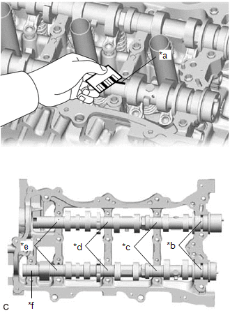 |
|
*a | Plastigage | |
*b | No. 1 Journal | |
*c | No. 2 journal | |
*d | No. 3 journal | |
*e | No. 4 journal | |
*f | No. 5 journal | | |
(b) for Bank 2:
(1) Clean the camshaft bearing caps, camshaft housing sub-assembly LH and camshaft journals.
(2) Place the camshafts on the camshaft housing sub-assembly LH.
| (3) Lay a strip of Plastigage across each camshaft journal. |
|
(4) Install the camshaft bearing caps.
Click here

NOTICE:
Do not turn the camshaft.
(5) Remove the camshaft bearing caps.
Click here

| (6) Measure the Plastigage at its widest point. Standard Oil Clearance: |
Item | Specified Condition | |
No. 1 journal | 0.032 to 0.063 mm (0.00126 to 0.00248 in.) | |
Other journals | 0.025 to 0.062 mm (0.000984 to 0.00244 in.) |
Maximum Oil Clearance: |
Item | Specified Condition | |
No. 1 journal | 0.10 mm (0.00394 in.) | |
Other journals | 0.10 mm (0.00394 in.) |
HINT:
- If the oil clearance is more than the maximum, replace the No. 3 camshaft sub-assembly or No. 4 camshaft sub-assembly.
- If necessary, replace the camshaft housing sub-assembly LH.
|
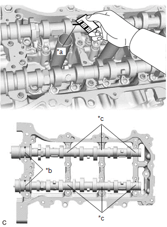 |
|
*a | Plastigage | |
*b | No. 1 Journal | |
*c | Other Journals | | |
18. INSPECT INTAKE MANIFOLD
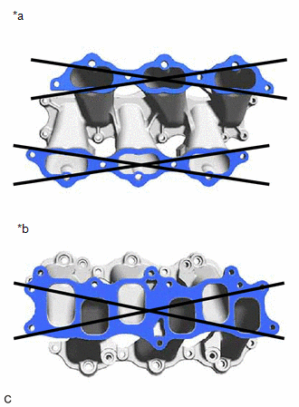
|
*a | Cylinder Head Side |
|
*b | Surge Tank Side |
(a) Cylinder head side:
(1)
Using a precision straightedge and feeler gauge, check the surface
which contacts the cylinder head sub-assembly and cylinder head LH for
warpage.
Maximum Warpage:
0.1 mm (0.00394 in.)
HINT:
If the warpage is more than the maximum, replace the intake manifold.
(b) Surge tank side:
(1)
Using a precision straightedge and feeler gauge, check the surface
which contacts the intake air surge tank assembly for warpage.
Maximum Warpage:
0.1 mm (0.00394 in.)
HINT:
If the warpage is more than the maximum, replace the intake manifold.
19. INSPECT EXHAUST MANIFOLD
| (a)
Using a precision straightedge and feeler gauge, check the surface
which contacts the cylinder head sub-assembly and cylinder head LH for
warpage. Maximum Warpage: 0.7 mm (0.0276 in.) HINT:
If the warpage is more than the maximum, replace the exhaust manifold. |
|
Installation
INSTALLATION
PROCEDURE
1. INSTALL ENGINE COVER BRACKET
(a) Install the engine cover bracket to the cylinder head cover sub-assembly LH with the bolt.
Torque:
10 N┬Ęm {102 kgf┬Ęcm, 7 ft┬Ęlbf}
2. INSTALL WATER FILLER BRACKET
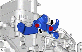
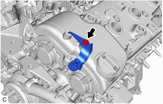
| (a) Temporarily install the water filler bracket to the camshaft housing sub-assembly LH with the 2 bolts. |
|
(b) Fully tighten the 2 bolts in the order shown in the illustration.
Torque:
8.0 N┬Ęm {82 kgf┬Ęcm, 71 in┬Ęlbf}
NOTICE:
Make
sure that the stopper of the water filler bracket is pressed against
the protrusion of the camshaft housing sub-assembly LH when fully
tightening the 2 bolts.
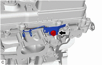
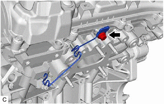
3. INSTALL WIRE HARNESS CLAMP BRACKET
(a) Install the wire harness clamp bracket to the camshaft housing sub-assembly with the bolt.
Torque:
30 N┬Ęm {306 kgf┬Ęcm, 22 ft┬Ęlbf}
(b) Install the wire harness clamp bracket to the camshaft housing sub-assembly LH with the bolt.
Torque:
30 N┬Ęm {306 kgf┬Ęcm, 22 ft┬Ęlbf}
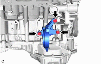
4. INSTALL DRIVE SHAFT BEARING BRACKET
(a) Install the drive shaft bearing bracket to the cylinder block sub-assembly with the 3 bolts.
Torque:
63.7 N┬Ęm {650 kgf┬Ęcm, 47 ft┬Ęlbf}
NOTICE:
Make sure that there is no oil on the threads of the bolts.
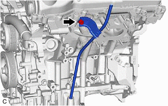
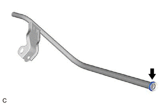
5. INSTALL ENGINE OIL LEVEL DIPSTICK GUIDE
(a) Install a new engine oil level dipstick guide O-ring to the engine oil level dipstick guide.
(b) Apply a light coat of engine oil to the engine oil level dipstick guide O-ring.
(c) Insert the engine oil level dipstick guide end into the oil pan sub-assembly.
(d) Install the engine oil level dipstick guide to the camshaft housing sub-assembly LH with the bolt.
Torque:
21 N┬Ęm {214 kgf┬Ęcm, 15 ft┬Ęlbf}
(e) Install the engine oil level dipstick to the engine oil level dipstick guide.
6. INSTALL WATER PUMP PULLEY
Click here

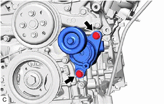
7. INSTALL V-RIBBED BELT TENSIONER ASSEMBLY
(a) Install the V-ribbed belt tensioner assembly with the 2 bolts.
Torque:
43 N┬Ęm {438 kgf┬Ęcm, 32 ft┬Ęlbf}
8. INSTALL NO. 2 IDLER PULLEY SUB-ASSEMBLY
Click here 
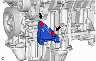
9. INSTALL NO. 1 COMPRESSOR MOUNTING BRACKET
| (a) Temporarily install the No. 1 compressor mounting bracket to the cylinder block sub-assembly with the 2 bolts. |
|
(b) Fully tighten the 2 bolts in the order shown in the illustration.
Torque:
43 N┬Ęm {438 kgf┬Ęcm, 32 ft┬Ęlbf}
10. INSTALL COMPRESSOR ASSEMBLY WITH MAGNETIC CLUTCH
Click here 
11. INSTALL GENERATOR ASSEMBLY
Click here 
12. INSTALL V-RIBBED BELT
Click here 
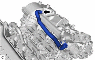
13. INSTALL NO. 2 VENTILATION HOSE
(a) Install the No. 2 ventilation hose to the cylinder head cover sub-assembly and slide the clip to secure it.
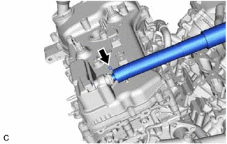
14. INSTALL VENTILATION HOSE
(a) Install the ventilation hose to the PCV valve (ventilation valve sub-assembly) and slide the clip to secure it.
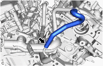
15. INSTALL NO. 2 WATER BY-PASS HOSE
(a) Install the No. 2 water by-pass hose to the water outlet and slide the clip to secure it.
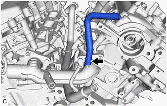
16. INSTALL NO. 3 WATER BY-PASS HOSE
(a) Install the No. 3 water by-pass hose to the water inlet pipe and slide the clip to secure it.
17. INSTALL VACUUM PUMP ASSEMBLY
Click here

18. INSTALL IGNITION COIL ASSEMBLY
Click here 
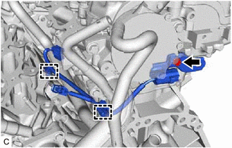
19. INSTALL SENSOR WIRE
(a) Engage the 2 clamps and install the sensor wire with the bolt.
Torque:
10 N┬Ęm {102 kgf┬Ęcm, 7 ft┬Ęlbf}
20. INSTALL KNOCK CONTROL SENSOR
Click here

Precaution
PRECAUTION
HINT:
- Any digits beyond the 1/100 mm (1/1000 in.) place for standard, minimum and maximum values should be used as a reference only.
- When both standard and maximum or minimum values are listed for an
inspection, use the standard value as a reference only and base any
judgments on the maximum and minimum values.
Reassembly
REASSEMBLY
PROCEDURE
1. INSTALL CYLINDER BLOCK WATER JACKET SPACER
| (a) Install the cylinder block water jacket spacer and cylinder block water jacket spacer LH to the cylinder block sub-assembly.
NOTICE: Firmly
press the cylinder block water jacket spacer into the cylinder block
sub-assembly and confirm that it is not protruding from the surface. |
|
2. INSTALL WATER INLET PIPE
| (a) Install the water inlet pipe with the 2 bolts. Torque:
10 N┬Ęm {102 kgf┬Ęcm, 7 ft┬Ęlbf} | |
3. INSTALL NO. 2 CYLINDER HEAD GASKET
Click here

4. INSTALL CYLINDER HEAD LH
(a) Place the cylinder head LH onto the cylinder block sub-assembly.
NOTICE:
- Do not allow oil to adhere to the bottom of the cylinder head LH.
- Gently lower the cylinder head LH in order not to damage the No. 2 cylinder head gasket with the bottom of the cylinder head LH.
HINT:
The cylinder head set bolts are tightened in 3 progressive steps.
(b) Apply a light coat of engine oil to the threads and under the heads of the cylinder head set bolts.
(c) Step 1:
| (1)
Using a 10 mm bi-hexagon socket wrench, install and uniformly tighten
the 8 cylinder head set bolts with 8 cylinder head set plate washers in
several steps in the order shown in the illustration. Torque: 36 N┬Ęm {367 kgf┬Ęcm, 27 ft┬Ęlbf} |
|
(d) Step 2:
(1) Mark each cylinder head set bolt head with paint as shown in the illustration.
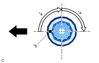
|
*a | Turn 90┬░ |
|
*b | Paint Mark |
 |
Front of Engine |
(2) Tighten the cylinder head set bolts 90┬░ in the order shown in step 1.
(e) Step 3:
(1) Tighten the cylinder head set bolts an additional 90┬░ in the order shown in step 1.
(2) Check that the paint marks are now facing rearward.
| (f) Tighten the 2 bolts in the order shown in the illustration.
Torque: 30 N┬Ęm {306 kgf┬Ęcm, 22 ft┬Ęlbf} HINT: Perform Inspection After Repair after replacing the cylinder head LH.
Click here  | |
5. INSTALL CYLINDER HEAD GASKET
Click here

6. INSTALL CYLINDER HEAD SUB-ASSEMBLY
(a) Place the cylinder head sub-assembly onto the cylinder block sub-assembly.
NOTICE:
- Do not allow oil to adhere to the bottom of the cylinder head sub-assembly.
- Gently lower the cylinder head sub-assembly in order not to damage the
cylinder head gasket with the bottom of the cylinder head sub-assembly.
HINT:
The cylinder head set bolts are tightened in 3 progressive steps.
(b) Apply a light coat of engine oil to the threads and under the heads of the cylinder head set bolts.
(c) Step 1:
| (1)
Using a 10 mm bi-hexagon socket wrench, install and uniformly tighten
the 8 cylinder head set bolts with 8 cylinder head set plate washers in
several steps in the order shown in the illustration. Torque: 36 N┬Ęm {367 kgf┬Ęcm, 27 ft┬Ęlbf} |
|
(d) Step 2:
(1) Mark each cylinder head set bolt head with paint as shown in the illustration.

|
*a | Turn 90┬░ |
|
*b | Paint Mark |
 |
Front of Engine |
(2) Tighten the cylinder head set bolts 90┬░ in the order shown in step 1.
(e) Step 3:
(1) Tighten the cylinder head set bolts an additional 90┬░ in the order shown in step 1.
(2) Check that the paint marks are now facing rearward.
HINT:
Perform Inspection After Repair after replacing the cylinder head sub-assembly.
Click here 
7. INSTALL REAR ENGINE OIL SEAL
(a) Place the rear engine oil seal retainer on wooden blocks.
(b) Apply MP grease to the lip of a new rear engine oil seal.
| (c) Using SST and a hammer, tap in the rear engine oil seal. SST: 09223-15030
SST: 09950-70010 09951-07100 Oil Seal Protrusion Height:
-0.5 to 0.5 mm (-0.0197 to 0.0197 in.)
NOTICE:
- Keep the lip free from foreign matter.
- Do not tap in the rear engine oil seal at an angle.
|
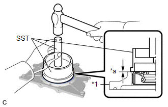 |
|
*1 | Rear Engine Oil Seal Retainer | |
*a | Oil Seal Protrusion Height | | |
8. INSTALL REAR ENGINE OIL SEAL RETAINER
| (a) Apply seal packing in a continuous line as shown in the illustration.
Seal Packing: Toyota Genuine Seal Packing Black, Three Bond 1207B or equivalent
Seal Packing Diameter: 2.0 to 3.0 mm (0.0787 to 0.118 in.)
NOTICE:
- Remove any oil from the contact surfaces.
- Install the rear engine oil seal retainer within 3 minutes of applying seal packing.
- Do not start the engine for at least 2 hours after installation.
| |
| (b) Install the rear engine oil seal retainer to the cylinder block sub-assembly with the 6 bolts.
Torque: 10 N┬Ęm {102 kgf┬Ęcm, 7 ft┬Ęlbf} Adhesive: Toyota Genuine Adhesive 1324, Three Bond 1324 or equivalent
NOTICE:
- Be sure to apply adhesive to the bolts (A) before installing them.
- Wipe off any seal packing that seeped out from the crankshaft position sensor insert part (B).
| |
9. INSTALL SENSOR WIRE
|
(a) Install the sensor wire to the cylinder head LH and cylinder block sub-assembly with the 3 bolts.
Torque: 10 N┬Ęm {102 kgf┬Ęcm, 7 ft┬Ęlbf} | |
10. INSTALL VALVE STEM CAP
| (a) Install the 24 valve stem caps to the cylinder head sub-assembly and cylinder head LH.
NOTICE:
- Install each part to its original position.
- Do not drop the valve stem caps into the cylinder head sub-assembly.
| |
11. INSTALL VALVE LASH ADJUSTER ASSEMBLY
(a) Inspect the valve lash adjuster assembly.
Click here 
| (b) Install the 24 valve lash adjuster assemblies to the cylinder head sub-assembly and cylinder head LH.
NOTICE: Install each part to its original position. | |
12. INSTALL NO. 1 VALVE ROCKER ARM SUB-ASSEMBLY
(a) Apply engine oil to the valve lash adjuster assembly tip and valve stem cap end.
| (b) Install the 24 No. 1 valve rocker arm sub-assemblies as shown in the illustration.
NOTICE: Install each part to its original position. |
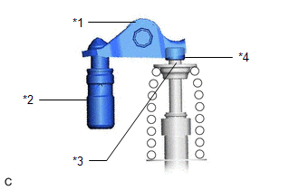 |
|
*1 | No. 1 Valve Rocker Arm Sub-assembly | |
*2 | Valve Lash Adjuster Assembly | |
*3 | Valve Stem | |
*4 | Valve Stem Cap | | |
13. INSTALL STRAIGHT PIN (for Bank 2)
HINT:
It is not necessary to remove the straight pin unless it is being replaced.
| (a) Using a plastic hammer, tap in a new straight pin to the camshaft housing sub-assembly LH.
Standard Protrusion Height: 7.7 to 8.3 mm (0.303 to 0.327 in.) |
|
14. INSTALL CAMSHAFT BEARING CAP SETTING RING PIN (for Bank 2)
HINT:
It is not necessary to remove the camshaft bearing cap setting ring pins unless they are being replaced.
| (a) Using a plastic hammer, tap 10 new camshaft bearing cap setting ring pins into the camshaft housing sub-assembly LH.
Standard Protrusion Height: 2.7 to 3.3 mm (0.106 to 0.130 in.) |
|
15. INSTALL NO. 3 CAMSHAFT SUB-ASSEMBLY
(a) Apply a light coat of engine oil to the No. 3 camshaft sub-assembly journals and camshaft housing sub-assembly LH.
(b) Install the No. 3 camshaft sub-assembly to the camshaft housing sub-assembly LH.
HINT:
Perform Inspection After Repair after replacing the No. 3 camshaft sub-assembly.
Click here 
16. INSTALL NO. 4 CAMSHAFT SUB-ASSEMBLY
(a) Apply a light coat of engine oil to the No. 4 camshaft sub-assembly journals and camshaft housing sub-assembly LH.
(b) Install the No. 4 camshaft sub-assembly to the camshaft housing sub-assembly LH.
HINT:
Perform Inspection After Repair after replacing the No. 4 camshaft sub-assembly.
Click here 
17. INSTALL CAMSHAFT BEARING CAP (for Bank 2)
| (a) Install the 2 oil control valve filters to the 2 camshaft bearing caps. |
|
(b) Apply engine oil to the 5 camshaft bearing caps.
| (c) Install the 5 camshaft bearing caps to the camshaft housing sub-assembly LH. |
|
| (d) Temporarily install and tighten the 8 bolts in the order shown in the illustration.
Torque: 10 N┬Ęm {102 kgf┬Ęcm, 7 ft┬Ęlbf} | |
18. INSTALL NO. 3 CHAIN TENSIONER ASSEMBLY
(a) Install the No. 3 chain tensioner assembly to the camshaft housing sub-assembly LH with the bolt.
Torque:
21 N┬Ęm {214 kgf┬Ęcm, 15 ft┬Ęlbf}
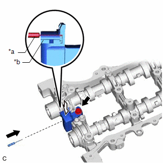
|
*a | Pin |
|
*b | Plunger |
 |
Push |
(b) While pushing down the No. 3 chain tensioner assembly, insert a 1.0 mm (0.0394 in.) diameter pin into the hole to secure it.
19. SET CAMSHAFT TIMING GEAR ASSEMBLY, CAMSHAFT TIMING EXHAUST GEAR ASSEMBLY AND NO. 2 CHAIN SUB-ASSEMBLY (for Bank 2)
| (a)
Align the mark plates (yellow) with the timing marks of the camshaft
timing gear assembly and camshaft timing exhaust gear assembly as shown
in the illustration. |
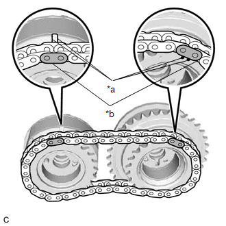 |
|
*a | Timing Mark | |
*b | Mark Plate | | |
(b)
Align the straight pins of the No. 3 camshaft sub-assembly and No. 4
camshaft sub-assembly with the pin holes of the camshaft timing gear
assembly and camshaft timing exhaust gear assembly. Temporarily install
the camshaft timing gear assembly and camshaft timing exhaust gear
assembly with the No. 2 chain sub-assembly installed.
NOTICE:
Be
careful not to damage the contact surface of the camshaft timing gear
assembly and camshaft timing exhaust gear assembly with the straight
pins of the No. 3 camshaft sub-assembly and No. 4 camshaft sub-assembly.
HINT:
Perform Inspection After Repair after replacing the camshaft timing gear assembly or camshaft timing exhaust gear assembly.
Click here 
20. TEMPORARILY INSTALL CAMSHAFT TIMING GEAR BOLT (for Intake Side of Bank 2)
Click here 
21. TEMPORARILY INSTALL CAMSHAFT TIMING GEAR BOLT (for Exhaust Side of Bank 2)
Click here 
22. INSTALL CAMSHAFT HOUSING SUB-ASSEMBLY LH
| (a) Make sure that the No. 1 valve rocker arm sub-assemblies are installed as shown in the illustration. |
 |
|
*1 | No. 1 Valve Rocker Arm Sub-assembly | |
*2 | Valve Lash Adjuster Assembly | |
*3 | Valve Stem | |
*4 | Valve Stem Cap | | |
| (b) Apply seal packing as shown in the illustration. Seal Packing:
Toyota Genuine Seal Packing Black, Three Bond 1207B or equivalent Seal Packing Application Specification: |
Area | Seal Packing Diameter | |
Continuous Line Area |
3.0 to 4.0 mm (0.118 to 0.157 in.) | |
Dashed Line Area |
4.0 to 4.5 mm (0.157 to 0.177 in.) |
NOTICE:
- Remove any oil from the contact surface.
- Install the camshaft housing sub-assembly LH within 3 minutes and tighten the bolts within 15 minutes of applying seal packing.
- Do not add engine oil for at least 2 hours after installation.
- Do not start the engine for at least 2 hours after installation.
|
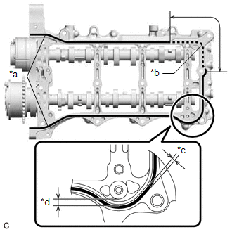 |
|
*a | Continuous Line Area | |
*b | Dashed Line Area | |
*c | 3.0 to 4.0 mm | |
*d | Separated by 4.0 to 6.0 mm (0.157 to 0.236 in.) | | |
(c) Install the camshaft housing sub-assembly LH and tighten the 15 bolts in the order shown in the illustration.
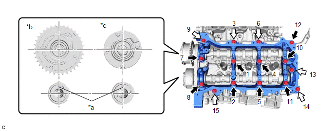
|
*a | Straight Pin |
*b | Intake Side |
|
*c | Exhaust Side |
- | - |
 |
Bolt (A) |
 |
Bolt (B) |
Torque:
28 N┬Ęm {286 kgf┬Ęcm, 21 ft┬Ęlbf}
NOTICE:
- When installing the camshaft housing sub-assembly LH, correctly position
the camshafts as shown in the illustration. Failure to do so may result
in damage due to contact between the pistons and valves. If a camshaft
is rotated, valve contact with a piston at TDC may occur.
- Make sure that the No. 1 valve rocker arm sub-assemblies are correctly installed.
- If it is necessary to loosen any of the bolts during installation,
remove the camshaft housing sub-assembly LH, clean the installation
surfaces, and reapply seal packing.
- If it is necessary to remove the camshaft housing sub-assembly LH during
installation, make sure that the previously applied seal packing does
not enter any oil passages.
Bolt Length:
|
Item | Length |
|
Bolt (A) | 68 mm (2.68 in.) |
|
Bolt (B) | 48 mm (1.89 in.) |
| (d) Tighten the 8 bolts in the order shown in the illustration.
Torque: 16 N┬Ęm {163 kgf┬Ęcm, 12 ft┬Ęlbf} | |
(e) Remove any protruding seal packing black.
NOTICE:
Be careful not to drop seal packing black into the cylinder head LH.
23. TIGHTEN CAMSHAFT TIMING GEAR BOLT (for Intake Side of Bank 2)
(a)
Using a wrench to hold the hexagonal portion of the No. 3 camshaft
sub-assembly, tighten the camshaft timing gear bolt of the camshaft
timing gear assembly.
Torque:
95 N┬Ęm {969 kgf┬Ęcm, 70 ft┬Ęlbf}
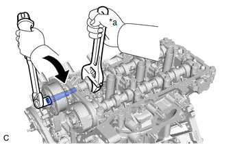
|
*a | Hold |
 |
Turn |
NOTICE:
Be careful not to damage the No. 3 camshaft sub-assembly, camshaft housing sub-assembly LH or spark plug tube with the wrench.
24. TIGHTEN CAMSHAFT TIMING GEAR BOLT (for Exhaust Side of Bank 2)
(a)
Using a wrench to hold the hexagonal portion of the No. 4 camshaft
sub-assembly, tighten the camshaft timing gear bolt of the camshaft
timing exhaust gear assembly.
Torque:
95 N┬Ęm {969 kgf┬Ęcm, 70 ft┬Ęlbf}
NOTICE:
Be careful not to damage the No. 4 camshaft sub-assembly, camshaft housing sub-assembly LH or spark plug tube with the wrench.
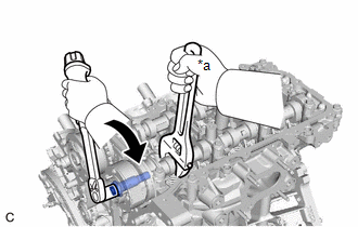
|
*a | Hold |
 |
Turn |
(b) Remove the pin from the No. 3 chain tensioner assembly.
25. INSTALL STRAIGHT PIN (for Bank 1)
HINT:
It is not necessary to remove the straight pin unless it is being replaced.
| (a) Using a plastic hammer, tap in a new straight pin to the camshaft housing sub-assembly.
Standard Protrusion Height: 7.7 to 8.3 mm (0.303 to 0.327 in.) |
|
26. INSTALL CAMSHAFT BEARING CAP SETTING RING PIN (for Bank 1)
HINT:
It is not necessary to remove the camshaft bearing cap setting ring pins unless they are being replaced.
| (a) Using a plastic hammer, tap 10 new camshaft bearing cap setting ring pins into the camshaft housing sub-assembly.
Standard Protrusion Height: 2.7 to 3.3 mm (0.106 to 0.130 in.) |
|
27. INSTALL CAMSHAFT
(a) Apply a light coat of engine oil to the camshaft journals and camshaft housing sub-assembly.
(b) Install the camshaft to the camshaft housing sub-assembly.
HINT:
Perform Inspection After Repair after replacing the camshaft.
Click here

28. INSTALL NO. 2 CAMSHAFT
(a) Apply a light coat of engine oil to the No. 2 camshaft journals and camshaft housing sub-assembly.
(b) Install the No. 2 camshaft to the camshaft housing sub-assembly.
HINT:
Perform Inspection After Repair after replacing the No. 2 camshaft.
Click here

29. INSTALL CAMSHAFT BEARING CAP (for Bank 1)
| (a) Install the 2 oil control valve filters to the 2 camshaft bearing caps. |
|
(b) Apply engine oil to the 5 camshaft bearing caps.
| (c) Install the 5 camshaft bearing caps to the camshaft housing sub-assembly. |
|
| (d) Install the fuel pump lifter housing to the camshaft housing sub-assembly. |
|
(e) Temporarily install and tighten the 9 bolts in the order shown in the illustration.
Torque:
10 N┬Ęm {102 kgf┬Ęcm, 7 ft┬Ęlbf}
Bolt Length:
|
Item | Length |
|
Bolt (A) | 40 mm (1.57 in.) |
|
Bolt (B) | 58 mm (2.28 in.) |
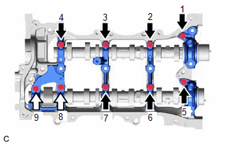
 |
Bolt (A) |
 |
Bolt (B) |
30. INSTALL NO. 2 CHAIN TENSIONER ASSEMBLY
(a) Install the No. 2 chain tensioner assembly to the camshaft housing sub-assembly with the bolt.
Torque:
21 N┬Ęm {214 kgf┬Ęcm, 15 ft┬Ęlbf}
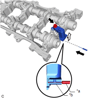
|
*a | Pin |
|
*b | Plunger |
 |
Push |
(b) While pushing up the No. 2 chain tensioner assembly, insert a 1.0 mm (0.0394 in.) diameter pin into the hole to secure it.
31. SET CAMSHAFT TIMING GEAR ASSEMBLY, CAMSHAFT TIMING EXHAUST GEAR ASSEMBLY AND NO. 2 CHAIN SUB-ASSEMBLY (for Bank 1)
| (a)
Align the mark plates (yellow) with the timing marks of the camshaft
timing gear assembly and camshaft timing exhaust gear assembly as shown
in the illustration. |
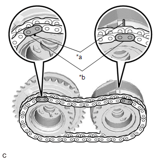 |
|
*a | Timing Mark | |
*b | Mark Plate | | |
(b)
Align the straight pins of the camshaft and No. 2 camshaft with the pin
holes of the camshaft timing gear assembly and camshaft timing exhaust
gear assembly. Temporarily install the camshaft timing gear assembly and
camshaft timing exhaust gear assembly with the No. 2 chain sub-assembly
installed.
NOTICE:
Be
careful not to damage the contact surface of the camshaft timing gear
assembly and camshaft timing exhaust gear assembly with the straight
pins of the camshaft and No. 2 camshaft.
HINT:
Perform Inspection After Repair after replacing the camshaft timing gear assembly or camshaft timing exhaust gear assembly.
Click here 
32. TEMPORARILY INSTALL CAMSHAFT TIMING GEAR BOLT (for Intake Side of Bank 1)
Click here 
33. TEMPORARILY INSTALL CAMSHAFT TIMING GEAR BOLT (for Exhaust Side of Bank 1)
Click here
34. INSTALL CAMSHAFT HOUSING SUB-ASSEMBLY
| (a) Make sure that the No. 1 valve rocker arm sub-assemblies are installed as shown in the illustration. |
 |
|
*1 | No. 1 Valve Rocker Arm Sub-assembly | |
*2 | Valve Lash Adjuster Assembly | |
*3 | Valve Stem | |
*4 | Valve Stem Cap | | |
| (b) Apply seal packing as shown in the illustration. Seal Packing:
Toyota Genuine Seal Packing Black, Three Bond 1207B or equivalent Seal Packing Diameter:
3.0 to 4.0 mm (0.118 to 0.157 in.)
NOTICE:
- Remove any oil from the contact surface.
- Install the camshaft housing sub-assembly within 3 minutes and tighten the bolts within 15 minutes of applying seal packing.
- Do not add engine oil for at least 2 hours after installation.
- Do not start the engine for at least 2 hours after installation.
|
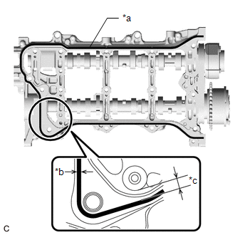 |
|
*a | Seal Packing | |
*b | 3.0 to 4.0 mm | |
*c | Separated by 4.0 to 6.0 mm (0.157 to 0.236 in.) | | |
(c) Install the camshaft housing sub-assembly and tighten the 15 bolts in the order shown in the illustration.
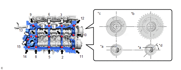
|
*a | Straight Pin |
*b | Intake Side |
|
*c | Exhaust Side |
*d | 45┬░ |
 |
Bolt (A) |
 |
Bolt (B) |
Torque:
28 N┬Ęm {286 kgf┬Ęcm, 21 ft┬Ęlbf}
NOTICE:
- When installing the camshaft housing sub-assembly, correctly position
the camshafts as shown in the illustration. Failure to do so may result
in damage due to contact between the pistons and valves. If a camshaft
is rotated, valve contact with a piston at TDC may occur.
- Make sure that the No. 1 valve rocker arm sub-assemblies are correctly installed.
- If it is necessary to loosen any of the bolts during installation,
remove the camshaft housing sub-assembly, clean the installation
surfaces, and reapply seal packing.
- If it is necessary to remove the camshaft housing sub-assembly during
installation, make sure that the previously applied seal packing does
not enter any oil passages.
Bolt Length:
|
Item | Length |
|
Bolt (A) | 68 mm (2.68 in.) |
|
Bolt (B) | 48 mm (1.89 in.) |
| (d) Tighten the 9 bolts in the order shown in the illustration.
Torque: 16 N┬Ęm {163 kgf┬Ęcm, 12 ft┬Ęlbf} | |
(e) Remove any protruding seal packing black.
NOTICE:
Be careful not to drop seal packing black into the cylinder head sub-assembly.
35. TIGHTEN CAMSHAFT TIMING GEAR BOLT (for Intake Side of Bank 1)
(a)
Using a wrench to hold the hexagonal portion of camshaft, tighten the
camshaft timing gear bolt of the camshaft timing gear assembly.
Torque:
95 N┬Ęm {969 kgf┬Ęcm, 70 ft┬Ęlbf}
NOTICE:
Be careful not to damage the camshaft, camshaft housing sub-assembly or spark plug tube with the wrench.
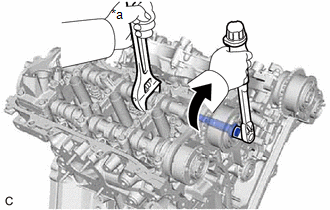
|
*a | Hold |
 |
Turn |
36. TIGHTEN CAMSHAFT TIMING GEAR BOLT (for Exhaust Side of Bank 1)
(a)
Using a wrench to hold the hexagonal portion of No. 2 camshaft, tighten
the camshaft timing gear bolt of the camshaft timing exhaust gear
assembly.
Torque:
95 N┬Ęm {969 kgf┬Ęcm, 70 ft┬Ęlbf}
NOTICE:
Be careful not to damage the No. 2 camshaft, camshaft housing sub-assembly or spark plug tube with the wrench.
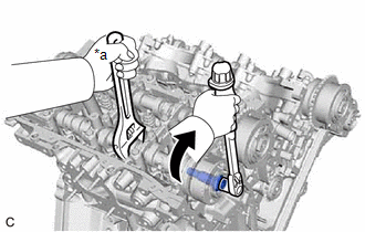
|
*a | Hold |
 |
Turn |
(b) Remove the pin from the No. 2 chain tensioner assembly.
37. INSTALL CRANKSHAFT TIMING GEAR KEY
| (a) Install the 2 crankshaft timing gear keys to the crankshaft. |
|
38. INSTALL CRANKSHAFT TIMING SPROCKET
| (a) Install the crankshaft timing sprocket to the crankshaft. |
|
39. INSTALL NO. 2 CHAIN VIBRATION DAMPER
| (a) Install the 2 No. 2 chain vibration dampers to the cylinder head LH and cylinder head sub-assembly. |
|
40. INSTALL NO. 1 CHAIN VIBRATION DAMPER
| (a) Install the No. 1 chain vibration damper to the cylinder head LH and cylinder block sub-assembly with the 2 bolts.
Torque: 22.5 N┬Ęm {229 kgf┬Ęcm, 17 ft┬Ęlbf} | |
41. INSTALL IDLE SPROCKET ASSEMBLY
(a) Apply a light coat of engine oil to the rotating surface of the No. 1 idle gear shaft.
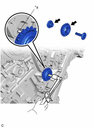
|
*a | Knock Pin |
 |
Light coat of engine oil |
(b)
Temporarily install the No. 1 idle gear shaft and idle sprocket
assembly with the No. 2 idle gear shaft while aligning the knock pin of
the No. 1 idle gear shaft with the pin hole of the cylinder block
sub-assembly.
NOTICE:
Make sure to install the No. 1 idle gear shaft installation in the correct direction.
HINT:
Check that there is no foreign matter on the No. 1 idle gear shaft or No. 2 idle gear shaft.
(c) Using a 10 mm hexagon socket wrench, tighten the No. 2 idle gear shaft.
Torque:
60 N┬Ęm {612 kgf┬Ęcm, 44 ft┬Ęlbf}
HINT:
After installing the idle sprocket assembly, check that the idle sprocket assembly turns smoothly.
42. INSTALL CHAIN SUB-ASSEMBLY
| (a) Align the mark plates and timing marks as shown in the illustration and install the chain sub-assembly.
HINT: The camshaft mark plates are yellow. |
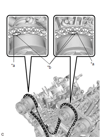 |
|
*a | Mark Plate | |
*b | Timing Mark | | |
| (b) Temporarily place the chain sub-assembly on the crankshaft as shown in the illustration. |
|
(c) Turn the camshaft timing gear assembly on bank 1 counterclockwise to tighten the chain sub-assembly between the banks.
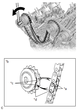
|
*a | Chain Plate |
|
*b | When the idle sprocket assembly is reused |
|
*c | Mark |
|
*d | Align |
 |
Turn |
NOTICE:
When
reusing the idle sprocket assembly, align the chain plate with the mark
where the mark plate had been in order to tighten the chain
sub-assembly between the banks.
| (d)
Align the mark plate and timing marks as shown in the illustration and
install the chain sub-assembly around the crankshaft timing sprocket. HINT:
The crankshaft mark plate is pink. |
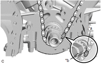 |
|
*a | Mark Plate | |
*b | Timing Mark | | |
(e) Temporarily tighten the crankshaft pulley set bolt to the crankshaft.
| (f) Turn the crankshaft clockwise to set it to the center line of the block bore (for Bank 1) (TDC /compression). |
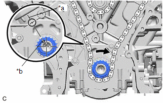 |
|
*a | Center Line | |
*b | Key Groove | | |
43. INSTALL CHAIN TENSIONER SLIPPER
| (a) Install the chain tensioner slipper to the cylinder block sub-assembly. |
|
44. INSTALL NO. 1 CHAIN TENSIONER ASSEMBLY
| (a) Turn the stopper plate clockwise to release the lock, and push the plunger deep into the No. 1 chain tensioner assembly. |
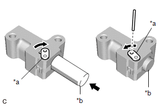 |
|
*a | Stopper Plate | |
*b | Plunger | | |
(b)
Turn the stopper plate counterclockwise to set the lock, and insert a
1.0 mm (0.0394 in.) diameter pin into the hole of the stopper plate.
| (c) Install the No. 1 chain tensioner assembly with the 2 bolts.
Torque: 10 N┬Ęm {102 kgf┬Ęcm, 7 ft┬Ęlbf} | |
(d) Remove the 1.0 mm (0.0394 in.) diameter pin from the No. 1 chain tensioner assembly.
45. INSPECT VALVE TIMING
(a) Check the camshaft timing marks.
NOTICE:
- Check each timing mark from a viewpoint directly in line with the center
of the camshaft and the timing mark on each camshaft timing gear
assembly and each camshaft timing exhaust gear assembly.
- If the timing marks are checked from any other viewpoint, the valve timing may appear misaligned.
(b) Check that each camshaft timing mark is positioned as shown in the illustration.
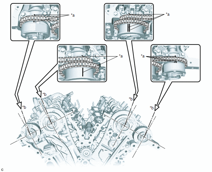
|
*a | Timing Mark |
*b | Viewpoint |
HINT:
For the camshaft or No. 3 camshaft sub-assembly:
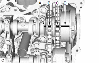
Be
sure to check the mark (A) at the point where the marks (B), (C) and
(D) are positioned in line. If the marks are checked from any other
viewpoint, they cannot be checked correctly.
(c) If the valve timing is misaligned, reinstall the chain sub-assembly.
(d) Remove the crankshaft pulley set bolt from the crankshaft.
46. INSTALL ENGINE WATER PUMP ASSEMBLY
| (a) Install a new water pump gasket and the engine water pump assembly with the 7 bolts.
Torque: 11 N┬Ęm {112 kgf┬Ęcm, 8 ft┬Ęlbf} | |
47. INSTALL TIMING CHAIN COVER ASSEMBLY
Click here

48. INSTALL TIMING CHAIN CASE OIL SEAL
Click here 
49. INSTALL TIMING CHAIN COVER PLATE
| (a)
Install a new timing chain cover gasket and the timing chain cover
plate to the timing chain cover assembly with the 4 bolts. Torque:
11 N┬Ęm {112 kgf┬Ęcm, 8 ft┬Ęlbf} | |
50. INSTALL NO. 1 OIL PAN BAFFLE PLATE
| (a) Install the No. 1 oil pan baffle plate to the crankshaft bearing cap set bolt. |
|
(b) Temporarily tighten the 2 bolts (A).
(c) Fully tighten the 8 bolts order shown in the illustration.
Torque:
10 N┬Ęm {102 kgf┬Ęcm, 7 ft┬Ęlbf}
51. INSTALL OIL FILTER BRACKET CLIP
| (a) Install the oil filter bracket clip to the oil pan sub-assembly. |
|
52. INSTALL OIL PAN SUB-ASSEMBLY
NOTICE:
If a stud bolt is deformed or its threads are damaged, replace it.
(a)
Using an E8 and E6 "TORX" socket wrench, install the 4 stud bolts to
the oil pan sub-assembly and cylinder block sub-assembly.
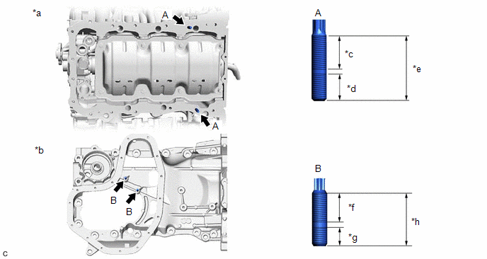
|
*a | Cylinder Block Sub-assembly Side |
*b | Oil Pan Sub-assembly Side |
|
*c | 20 mm (0.787 in.) |
*d | 13 mm (0.512 in.) |
|
*e | 35 mm (1.38 in.) |
*f | 16 mm (0.630 in.) |
|
*g | 9 mm (0.354 in.) |
*h | 27 mm (1.06 in.) |
Torque:
Stud bolt (A) :
10 N┬Ęm {102 kgf┬Ęcm, 7 ft┬Ęlbf}
Stud bolt (B) :
4.0 N┬Ęm {41 kgf┬Ęcm, 35 in┬Ęlbf}
| (b) w/ Oil Cooler: (1) Using an E8 "TORX" socket wrench, install the 2 stud bolts to the oil pan sub-assembly.
Torque: 10 N┬Ęm {102 kgf┬Ęcm, 7 ft┬Ęlbf} |
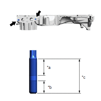 |
|
*a | 20 mm (0.787 in.) | |
*b | 13 mm (0.512 in.) | |
*c | 35 mm (1.38 in.) | | |
(c) Install the oil pan sub-assembly.
Click here

53. INSTALL ENGINE OIL LEVEL SENSOR
Click here 
54. INSTALL OIL STRAINER SUB-ASSEMBLY
(a) Apply a light coat of engine oil to a new oil strainer gasket.
| (b)
Align the protrusion of the oil strainer gasket with the cutout of the
oil strainer sub-assembly, and install the oil strainer gasket to the
oil strainer sub-assembly. | |
| (c) Install the oil strainer sub-assembly to the timing chain cover assembly with the 2 nuts.
Torque: 10 N┬Ęm {102 kgf┬Ęcm, 7 ft┬Ęlbf} | |
55. INSTALL NO. 2 OIL PAN SUB-ASSEMBLY
NOTICE:
If a stud bolt is deformed or its threads are damaged, replace it.
| (a) Using an E6 "TORX" socket wrench, install the 2 stud bolts to the oil pan sub-assembly as shown in the illustration.
Torque: 4.0 N┬Ęm {41 kgf┬Ęcm, 35 in┬Ęlbf} |
 |
|
*a | 9 mm (0.354 in.) | |
*b | 19 mm (0.748 in.) | | |
| (b) Apply seal packing in a continuous line as shown in the illustration.
Seal Packing: Toyota Genuine Seal Packing Black, Three Bond 1207B or equivalent
Seal Packing Diameter: 3.0 to 4.0 mm (0.118 to 0.157 in.)
NOTICE:
- Remove any oil from the contact surfaces.
- Install the No. 2 oil pan sub-assembly within 3 minutes of applying seal packing.
- Do not start the engine for at least 2 hours after installation.
| |
| (c) Install the No. 2 oil pan sub-assembly with the 15 bolts and 2 nuts as shown in the illustration.
Torque: 10 N┬Ęm {102 kgf┬Ęcm, 7 ft┬Ęlbf} | |
56. INSTALL ENGINE OIL PRESSURE SWITCH ASSEMBLY
Click here

57. INSTALL OIL FILTER CAP ASSEMBLY
Click here 
58. INSTALL OIL PAN DRAIN PLUG
| (a) Install a new oil pan drain plug gasket and the oil pan drain plug to the No. 2 oil pan sub-assembly.
Torque: 40 N┬Ęm {408 kgf┬Ęcm, 30 ft┬Ęlbf} | |
59. INSTALL SPARK PLUG TUBE GASKET
| (a) Install 6 new spark plug tube gaskets to the cylinder head cover sub-assembly and cylinder head cover sub-assembly LH. |
|
60. INSTALL CYLINDER HEAD COVER SUB-ASSEMBLY LH
| (a) Install 3 new No. 2 cylinder head cover gaskets to the cylinder head cover sub-assembly LH.
NOTICE: Make
sure that there is no oil or foreign matter inside the groove of the
camshaft housing sub-assembly LH or on the contact surfaces of the
cylinder head cover sub-assembly LH and timing chain cover assembly.
Clean if necessary. | |
| (b) Install a new camshaft bearing cap oil hole gasket LH to the camshaft bearing cap. |
|
(c) Apply seal packing as shown in the illustration.
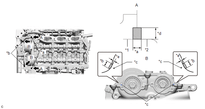
|
*1 | Timing Chain Cover Assembly |
*2 | Camshaft Housing Sub-assembly LH |
|
*a | Seal Packing (Diameter 2.0 to 3.0 mm (0.0787 to 0.118 in.)) |
*b | Seal Packing (Diameter 5.0 to 7.0 mm (0.197 to 0.276 in.)) |
|
*c | Mark |
*d | 5.0 to 10 mm (0.197 to 0.394 in.) |
|
*e | Thickness: 1.0 to 3.0 mm (0.0394 to 0.118 in.) |
- | - |
 |
Seal Packing | - |
- |
Seal Packing:
Toyota Genuine Seal Packing Black, Three Bond 1207B or equivalent
Seal Packing Application Specification:
|
Area | Seal Packing Diameter |
|
(A) | Thickness: 5 to 10 mm (0.197 to 0.394 in.)
Width: 2 to 3 mm (0.0787 to 0.118 in.) |
|
(B) | Thickness: 1 to 3 mm (0.0394 to 0.118 in.)
Width: 5 to 7 mm (0.197 to 0.276 in.) |
NOTICE:
- Remove any oil from the contact surfaces.
- Install the cylinder head cover sub-assembly LH within 3 minutes and
tighten the bolts within 15 minutes of applying seal packing.
- Do not start the engine for at least 2 hours after installation.
(d) Apply a light coat of engine oil to
the 2 new O-rings of the 2 VVT sensors (for Exhaust Side of Bank 2 and
for Intake Side of Bank 2).
NOTICE:
If
reusing the 2 VVT sensors (for Exhaust Side of Bank 2 and for Intake
Side of Bank 2), be sure to inspect them before installation.
(e) Clean the 2 bolts and 2 bolt holes of the VVT sensors (for Exhaust Side of Bank 2 and for Intake Side of Bank 2).
| (f)
Apply adhesive to 2 or 3 threads at the end of the 2 bolts of the VVT
sensors (for Exhaust Side of Bank 2 and for Intake Side of Bank 2). Adhesive:
Toyota Genuine Adhesive 1324, Three Bond 1324 or equivalent |
|
| (g)
Install the cylinder head cover sub-assembly LH with the 16 bolts and 2
VVT sensors (for Exhaust Side of Bank 2 and for Intake Side of Bank 2)
in the order shown in the illustration. Torque: 10 N┬Ęm {102 kgf┬Ęcm, 7 ft┬Ęlbf}
NOTICE:
- If a VVT sensor (for Exhaust Side of Bank 2 or for Intake Side of Bank 2) has been struck or dropped, replace it.
- Make sure that the 2 O-rings are not cracked or moved out of place when
installing the 2 VVT sensors (for Exhaust Side of Bank 2 and for Intake
Side of Bank 2).
HINT: After tightening all bolts, check the tightening torque of the bolts (1) and (18). Retighten them if necessary. |
|
| (h) Install the No. 1 V-bank cover bracket to the cylinder head cover sub-assembly LH.
Torque: 10 N┬Ęm {102 kgf┬Ęcm, 7 ft┬Ęlbf} | |
61. INSTALL CYLINDER HEAD COVER SUB-ASSEMBLY
| (a) Install 3 new cylinder head cover gaskets to the cylinder head cover sub-assembly.
NOTICE: Make
sure that there is no oil or foreign matter inside the groove of the
camshaft housing sub-assembly or on the contact surfaces of the cylinder
head cover sub-assembly and timing chain cover assembly. Clean if
necessary. | |
| (b) Install a new camshaft bearing cap oil hole gasket to the camshaft bearing cap. |
|
(c) Apply seal packing as shown in the illustration.
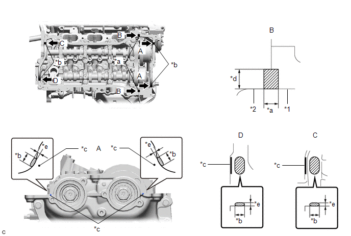
|
*1 | Timing Chain Cover Assembly |
*2 | Camshaft Housing Sub-assembly |
|
*a | Seal Packing (Diameter 2.0 to 3.0 mm (0.0787 to 0.118 in.)) |
*b | Seal Packing (Diameter 5.0 to 7.0 mm (0.197 to 0.276 in.)) |
|
*c | Mark |
*d | 5.0 to 10 mm (0.197 to 0.394 in.) |
|
*e | Thickness: 1.0 to 3.0 mm (0.0394 to 0.118 in.) |
- | - |
 |
Seal Packing | - |
- |
Seal Packing:
Toyota Genuine Seal Packing Black, Three Bond 1207B or equivalent
NOTICE:
- Remove any oil from the contact surfaces.
- Install the cylinder head cover sub-assembly within 3 minutes and tighten the bolts within 15 minutes of applying seal packing.
- Do not start the engine for at least 2 hours after installation.
(d) Apply a light coat of engine oil to
the 2 new O-rings of the 2 VVT sensors (for Exhaust Side of Bank 1 and
for Intake Side of Bank 1).
NOTICE:
If
reusing the 2 VVT sensors (for Exhaust Side of Bank 1 and for Intake
Side of Bank 1), be sure to inspect them before installation.
(e) Clean the 2 bolts and 2 bolt holes of the VVT sensors (for Exhaust Side of Bank 1 and for Intake Side of Bank 1).
| (f)
Apply adhesive to 2 or 3 threads at the end of the 2 bolts of the VVT
sensors (for Exhaust Side of Bank 1 and for Intake Side of Bank 1). Adhesive:
Toyota Genuine Adhesive 1324, Three Bond 1324 or equivalent |
|
| (g)
Install the cylinder head cover sub-assembly with the 15 bolts and 2
VVT sensors (for Exhaust Side of Bank 1 and for Intake Side of Bank 1)
in the order shown in the illustration. Torque: 10 N┬Ęm {102 kgf┬Ęcm, 7 ft┬Ęlbf}
NOTICE:
- If a VVT sensor (for Exhaust Side of Bank 1 or for Intake Side of Bank 1) has been struck or dropped, replace it.
- Make sure that the 2 O-rings are not cracked or moved out of place when
installing the 2 VVT sensors (for Exhaust Side of Bank 1 and for Intake
Side of Bank 1).
HINT: After tightening all bolts, check the tightening torque of the bolts (1) and (17). Retighten them if necessary. |
|
| (h) Install the No. 1 engine cover sub-assembly to the cylinder head cover sub-assembly with the 2 clips. |
|
62. INSTALL WATER OUTLET
|
(a) Install 2 new No. 2 water inlet housing gaskets to the water outlet. |
|
(b) Install the water outlet to the cylinder head sub-assembly and cylinder head LH with the 4 bolts and 2 nuts.
Torque:
10 N┬Ęm {102 kgf┬Ęcm, 7 ft┬Ęlbf}
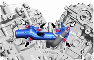
 |
Bolt |
 |
Nut |
63. INSTALL ENGINE COOLANT TEMPERATURE SENSOR
Click here 
64. INSTALL CRANKSHAFT POSITION SENSOR
Click here 
65. INSTALL CRANKSHAFT POSITION SENSOR PROTECTOR
Click here 
66. INSTALL CAMSHAFT TIMING OIL CONTROL SOLENOID ASSEMBLY (for Intake Side of Bank 2)
Click here 
67. INSTALL CAMSHAFT TIMING OIL CONTROL SOLENOID ASSEMBLY (for Exhaust Side of Bank 2)
Click here 
68. INSTALL CAMSHAFT TIMING OIL CONTROL SOLENOID ASSEMBLY (for Exhaust Side of Bank 1)
Click here 
69. INSTALL CAMSHAFT TIMING OIL CONTROL SOLENOID ASSEMBLY (for Intake Side of Bank 1)
Click here 
70. INSTALL WATER INLET WITH THERMOSTAT SUB-ASSEMBLY
Click here 
71. INSTALL WATER BY-PASS HOSE
| (a)
Install the water by-pass hose to the water inlet pipe and water inlet
with thermostat sub-assembly and slide the 2 clips to secure it. | |
72. INSTALL FRONT NO. 1 ENGINE MOUNTING BRACKET LH
NOTICE:
If a stud bolt is deformed or its threads are damaged, replace it.
| (a) Using an E8 "TORX" socket wrench, install the 2 stud bolts to the front No. 1 engine mounting bracket LH.
Torque: 10 N┬Ęm {102 kgf┬Ęcm, 7 ft┬Ęlbf} |
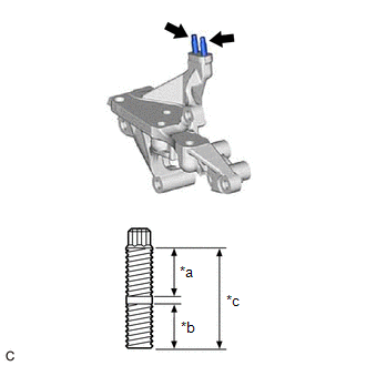 |
|
*a | 14 mm (0.551 in.) | |
*b | 13 mm (0.512 in.) | |
*c | 29 mm (1.14 in.) | | |
| (b)
Install the front No. 1 engine mounting bracket LH to the timing chain
cover assembly with the 7 bolts in the order shown in the illustration. Torque:
54 N┬Ęm {551 kgf┬Ęcm, 40 ft┬Ęlbf} NOTICE: Make sure that there is no oil on the threads of the bolts.
Bolt Length: |
Item | Length | |
Bolt (A) | 115 mm (4.53 in.) | |
Bolt (B) | 85 mm (3.35 in.) | |
Bolt (C) | 40 mm (1.57 in.) | |
|
73. INSTALL CRANKSHAFT PULLEY
Click here

74. INSTALL CYLINDER BLOCK WATER DRAIN COCK SUB-ASSEMBLY
| (a) Apply adhesive to the cylinder block water drain cock sub-assembly.
Adhesive: Toyota Genuine Adhesive 1324, Three Bond 1324 or equivalent
NOTICE: Install the cylinder block water drain cock sub-assembly within 3 minutes of applying adhesive. |
|
| (b) Install the cylinder block water drain cock sub-assembly to the cylinder block sub-assembly as shown in the illustration.
Torque: 25 N┬Ęm {255 kgf┬Ęcm, 18 ft┬Ęlbf}
NOTICE:
- Do not rotate the cylinder block water drain cock sub-assembly more than
1 revolution (360┬░) after tightening it to the specified torque.
- Do not loosen the cylinder block water drain cock sub-assembly after setting it to the correct position.
| |
(c) Install the cylinder block water drain cock plug to the cylinder block water drain cock sub-assembly.
Torque:
12.7 N┬Ęm {130 kgf┬Ęcm, 9 ft┬Ęlbf}
75. INSTALL PCV VALVE (VENTILATION VALVE SUB-ASSEMBLY)
Click here 
76. INSTALL SPARK PLUG
Click here 
77. INSTALL OIL FILLER CAP SUB-ASSEMBLY
| (a) Install a new oil filler cap gasket to the oil filler cap sub-assembly. |
|
| (b) Install the oil filler cap sub-assembly to the cylinder head cover sub-assembly LH. |
|
Removal
REMOVAL
CAUTION / NOTICE / HINT
The
necessary procedures (adjustment, calibration, initialization or
registration) that must be performed after parts are removed and
installed, or replaced during engine unit removal/installation are shown
below.
Necessary Procedure After Parts Removed/Installed/Replaced |
Replaced Part or Performed Procedure |
Necessary Procedure | Effect/Inoperative Function when Necessary Procedure not Performed |
Link |
|
Battery terminal is disconnected/reconnected |
Perform steering sensor zero point calibration |
Lane departure alert system (w/ Steering Control) |
 |
|
Pre-collision system |
|
Intelligent Clearance Sonar System*1 |
|
Lighting System (for Gasoline Model with Cornering Light) |
|
Memorize steering angle neutral point |
Parking Assist Monitor System |
 |
|
Panoramic View Monitor System |
 |
|
Replacement of ECM | Vehicle Identification Number (VIN) registration |
MIL comes on |
 |
|
ECU communication ID registration (Immobiliser system) |
Engine start function |
 |
- Replacement of throttle body with motor assembly
- Cleaning the deposits from the throttle body with motor assembly
- Replacement of engine assembly
- Replacement of cylinder head sub-assembly
- Replacement of camshaft (for intake or exhaust camshaft)
- Replacement of camshaft timing gear assembly
- Replacement of camshaft timing exhaust gear assembly
- Replacement of fuel injector assembly (for port injection)
- Replacement of fuel injector assembly (for direct injection)
- Replacement of fuel pump assembly (for high pressure side)
- Replacement of engine coolant temperature sensor
- Replacement of spark plug
- Replacement of ignition coil assembly
- Air leaks from intake system
- Gas leak from exhaust system is repaired
- Replacement of knock control sensor
| Inspection after repair |
- Poor idle, etc.
- Engine start function, etc.
|
 |
|
Replacement of automatic transaxle assembly |
- Perform reset memory
- Input transaxle compensation code into ECM
- Perform road test to allow ECM to learn
|
- Large shift shock
- Deterioration of fuel efficiency
|
 for Initialization for Initialization
 for Registration for Registration |
|
Replacement of ECM (If transaxle compensation code read from ECM) |
- Perform reset memory*2
- Transfer transaxle compensation code
- Perform road test to allow ECM to learn
|
| Replacement of ECM
(If transaxle compensation code not read from ECM) |
- Perform reset memory*2
- Reset transaxle compensation code
- Perform road test to allow ECM to learn
|
| Replacement of automatic transaxle fluid |
ATF thermal degradation estimate reset |
The value of the Data List item "ATF Thermal Degradation Estimate" is not estimated correctly |
 |
|
Replacement of ECM | Code registration (Smart Key System (for Start Function)) |
- Wireless Door Lock Control System
- Smart Key System (for Entry Function)
- Smart Key System (for Start Function)
- Steering lock function
|
 |
|
Suspension, tires, etc. |
- Measure ultrasonic sensor detection angle
- Ultrasonic sensor detection angle registration
|
- Intelligent Clearance Sonar System
- Intuitive Parking Assist System
|
 |
|
Rear television camera assembly optical axis adjustment (Back camera position setting) |
Parking Assist Monitor System |
 for Initialization for Initialization
 for Calibration for Calibration |
- Parking assist ECU initialization
- Adjust steering angle
- Television camera assembly optical axis adjustment (Back camera position setting)
| Panoramic View Monitor System |
 for Initialization for Initialization
 for Calibration for Calibration |
|
Perform headlight ECU sub-assembly LH initialization |
Lighting system (for Gasoline Model with Cornering Light) |
 |
|
Front wheel alignment adjustment |
Perform system variant learning and acceleration sensor zero point calibration. |
- VSC is disabled or malfunctions
- DTCs are output
- Slip indicator light illuminates
- ABS warning light illuminates
|
 |
- *1: When performing learning using the Techstream.
Click here 
- *2: Not necessary when ECM replaced with new one.
PROCEDURE
1. REMOVE KNOCK CONTROL SENSOR
Click here 
2. REMOVE SENSOR WIRE
| (a) Disengage the 2 clamps and remove the bolt and sensor wire. |
|
3. REMOVE IGNITION COIL ASSEMBLY
Click here

4. REMOVE VACUUM PUMP ASSEMBLY
Click here

5. REMOVE NO. 3 WATER BY-PASS HOSE
| (a) Slide the clip and remove the No. 3 water by-pass hose from the water inlet pipe. |
|
6. REMOVE NO. 2 WATER BY-PASS HOSE
| (a) Slide the clip and remove the No. 2 water by-pass hose from the water outlet. |
|
7. REMOVE VENTILATION HOSE
| (a) Slide the clip and remove the ventilation hose from the PCV valve (ventilation valve sub-assembly). |
|
8. REMOVE NO. 2 VENTILATION HOSE
| (a) Slide the clip and remove the No. 2 ventilation hose from the cylinder head cover sub-assembly. |
|
9. REMOVE V-RIBBED BELT
Click here 
10. REMOVE GENERATOR ASSEMBLY
Click here

11. REMOVE COMPRESSOR ASSEMBLY WITH MAGNETIC CLUTCH
Click here 
12. REMOVE NO. 1 COMPRESSOR MOUNTING BRACKET
| (a) Remove the 2 bolts and No. 1 compressor mounting bracket from the cylinder block sub-assembly. |
|
13. REMOVE NO. 2 IDLER PULLEY SUB-ASSEMBLY
Click here

14. REMOVE V-RIBBED BELT TENSIONER ASSEMBLY
| (a) Remove the 2 bolts and V-ribbed belt tensioner assembly. |
|
15. REMOVE WATER PUMP PULLEY
Click here

16. REMOVE ENGINE OIL LEVEL DIPSTICK GUIDE
(a) Remove the engine oil level dipstick from the engine oil level dipstick guide.
| (b) Remove the bolt and engine oil level dipstick guide from the camshaft housing sub-assembly LH and oil pan sub-assembly. |
|
| (c) Remove the engine oil level dipstick guide O-ring from the engine oil level dipstick guide. |
|
17. REMOVE DRIVE SHAFT BEARING BRACKET
| (a) Remove the 3 bolts and drive shaft bearing bracket from the cylinder block sub-assembly. |
|
18. REMOVE WIRE HARNESS CLAMP BRACKET
| (a) Remove the bolt and wire harness clamp bracket from the camshaft housing sub-assembly LH. |
|
| (b) Remove the bolt and wire harness clamp bracket from the camshaft housing sub-assembly. |
|
19. REMOVE WATER FILLER BRACKET
| (a) Remove the 2 bolts and water filler bracket from the camshaft housing sub-assembly LH. |
|
20. REMOVE ENGINE COVER BRACKET
| (a) Remove the bolt and engine cover bracket from the cylinder head cover sub-assembly LH. |
|


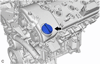
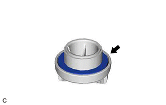


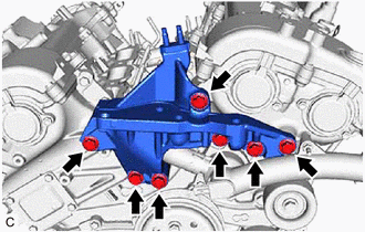
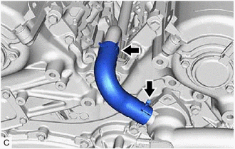


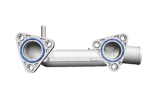
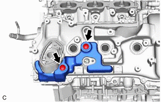
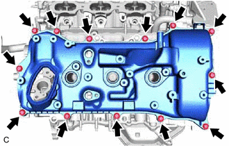
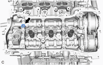
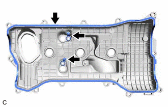
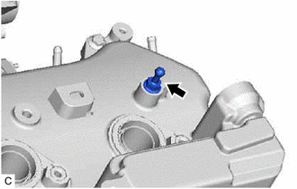
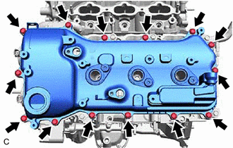
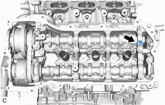
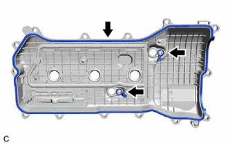
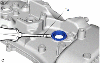
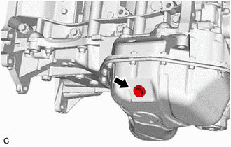


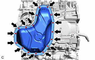
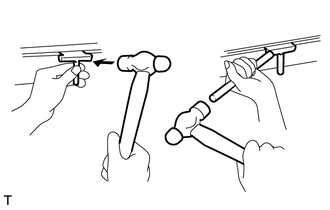
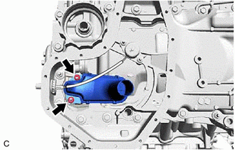
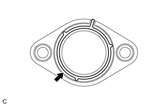


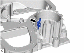
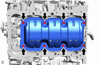
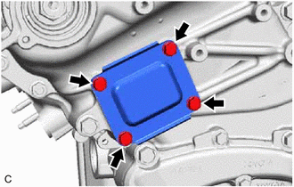


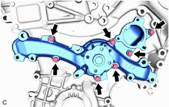


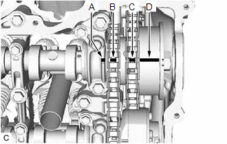

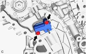
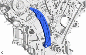

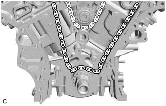
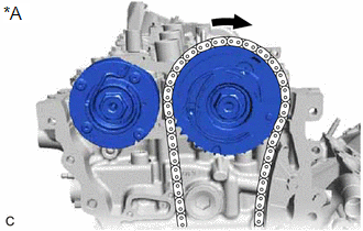
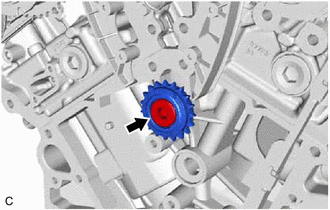
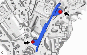
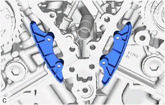
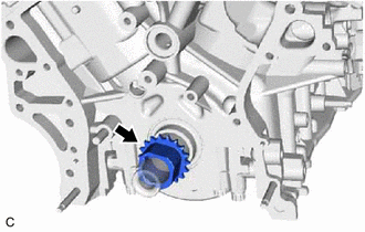
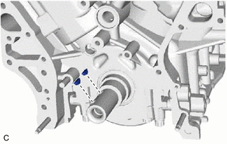


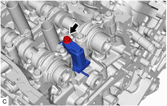

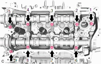
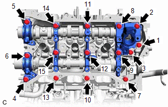
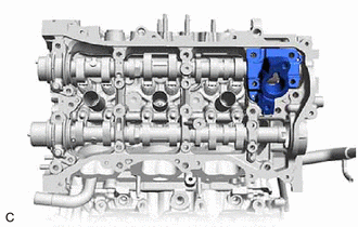
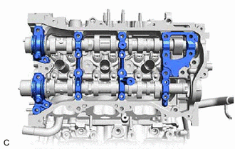
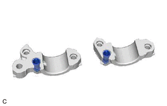
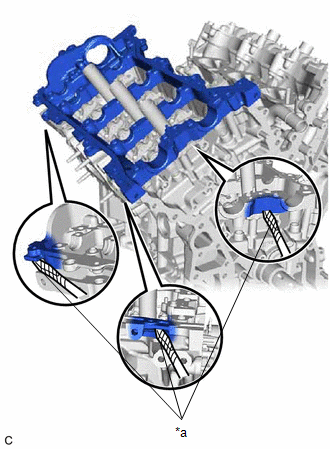


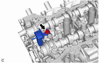

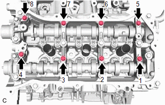
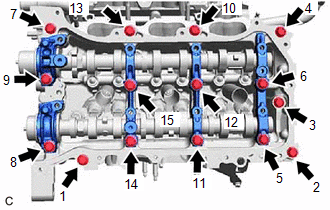
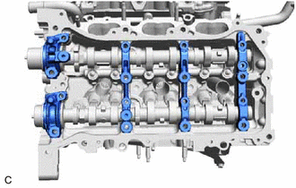
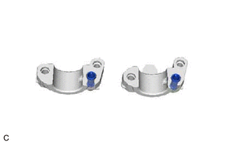
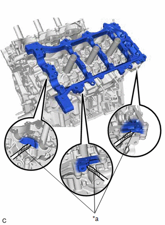
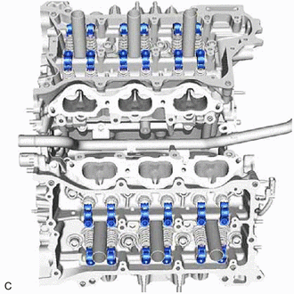
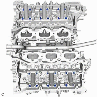
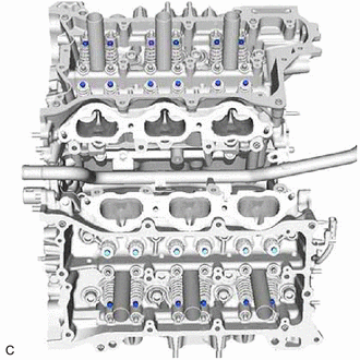
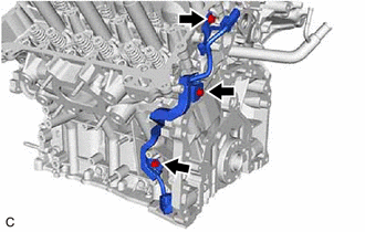
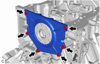


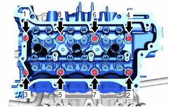

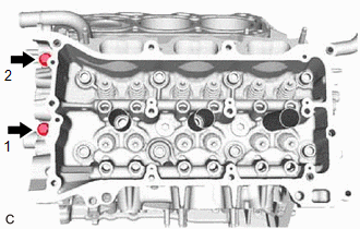
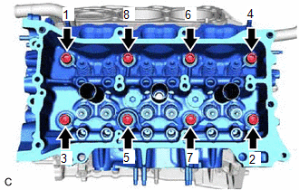

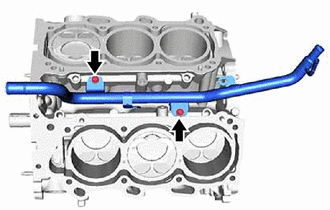
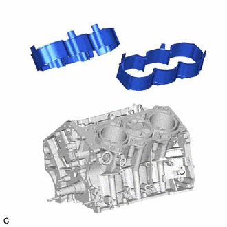
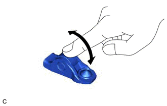

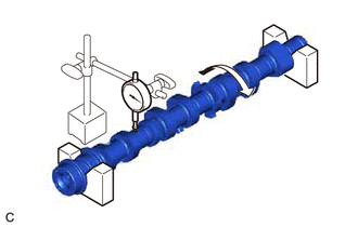
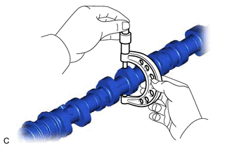
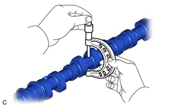

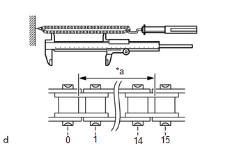
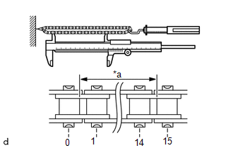
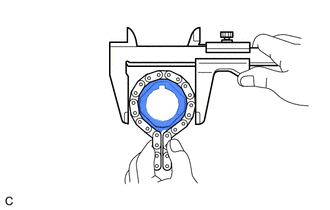
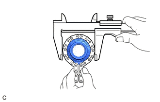
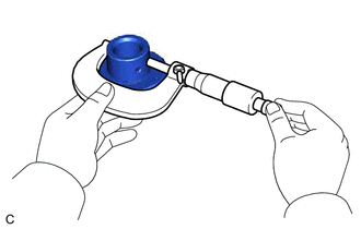
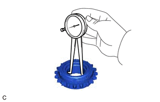

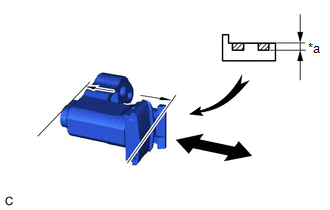
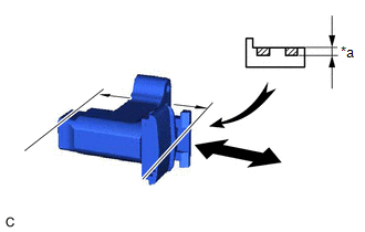
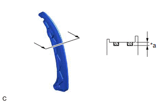
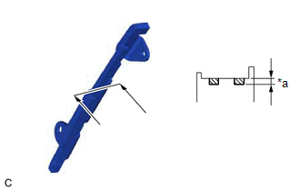
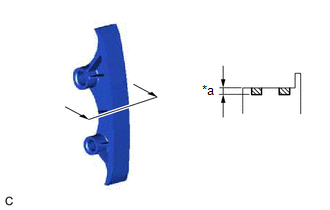


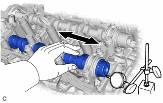


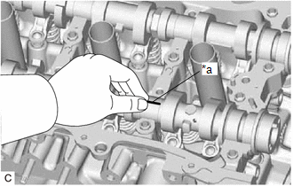


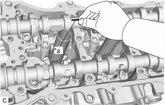


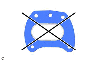
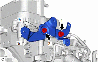


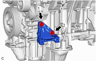


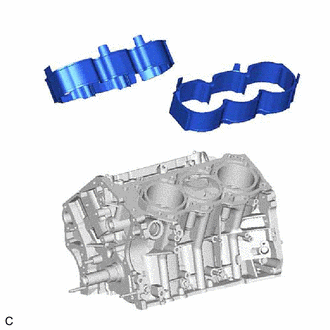
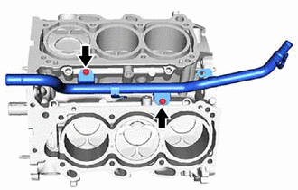

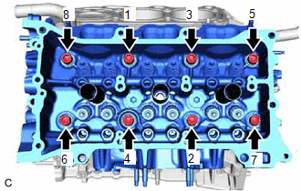


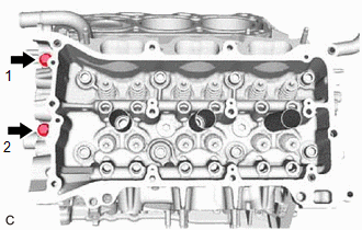

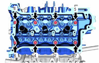


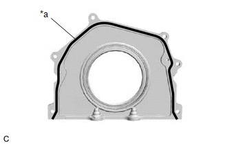
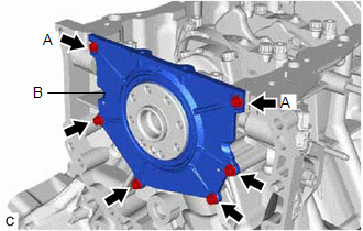
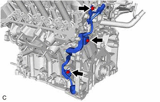
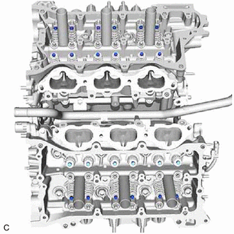

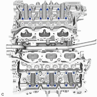

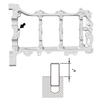
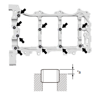


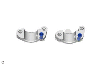
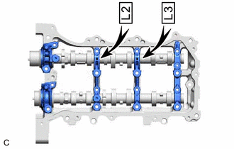
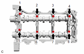


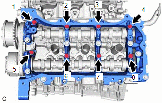


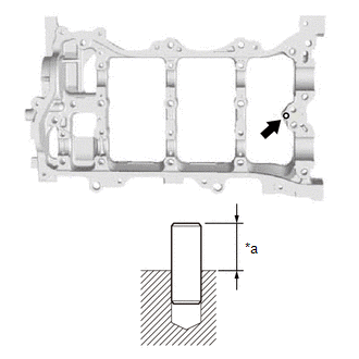
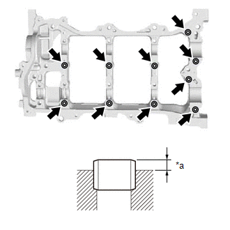


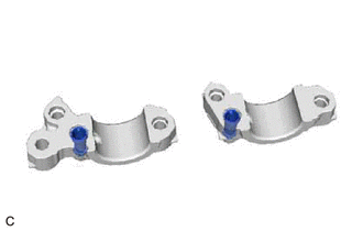
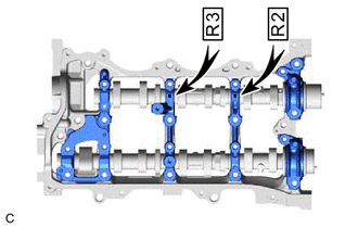
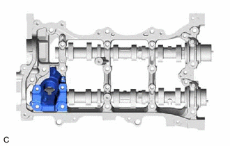


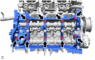


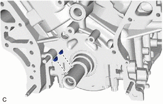
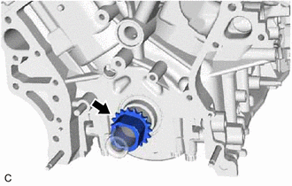
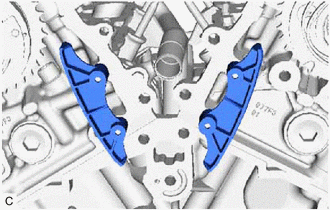
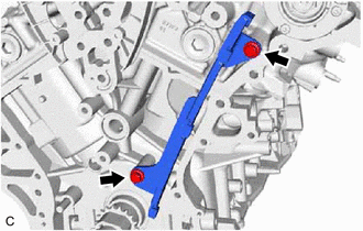


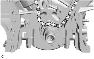


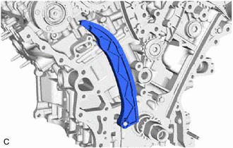

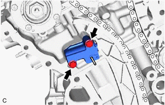


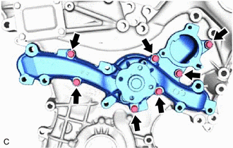


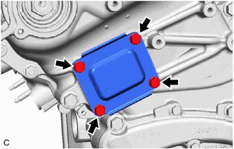
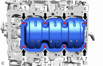
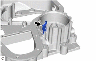


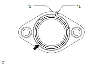
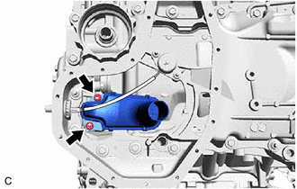

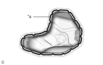
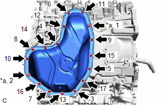


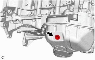
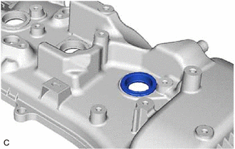
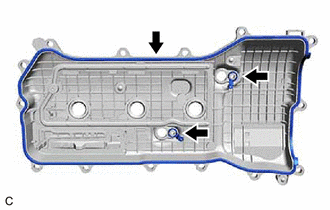
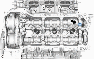


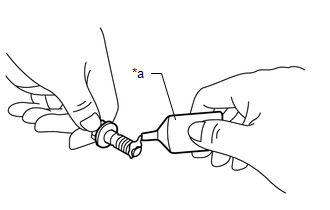
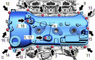
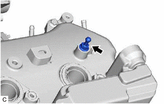
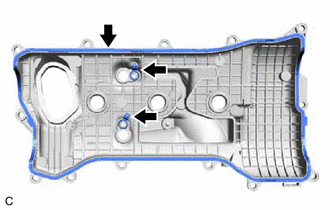
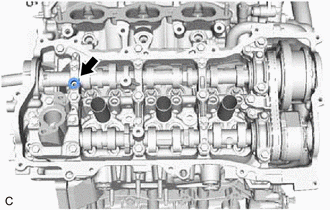


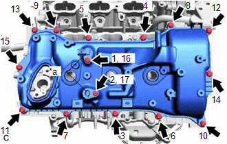
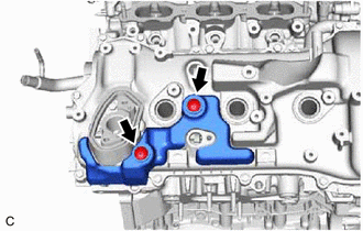
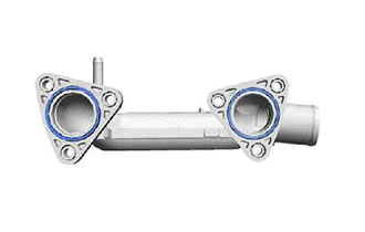


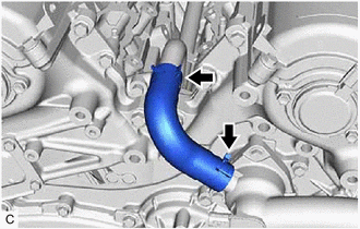

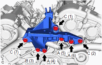

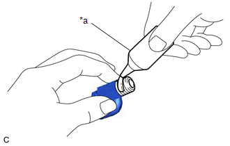
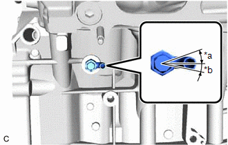


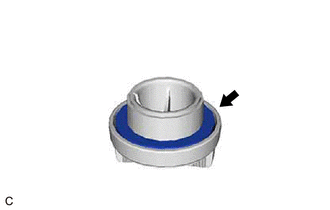
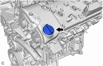


 for Initialization
 for Registration


 for Initialization
 for Calibration
 for Initialization
 for Calibration


