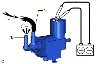
COMPONENTS ILLUSTRATION *1 AIR CLEANER ASSEMBLY WITH AIR CLEANER HOSE *2 COOL AIR INTAKE DUCT SEAL *3 INLET AIR CLEANER ASSEMBLY *4 VACUUM SWITCHING VALVE (for Active Control Engine Mount System) *5 VACUUM HOSE *6 ENGINE WIRE *7 NO. 1 FUEL VAPOR FEED HOSE *8 NO. 2 VENTILATION HOSE N*m (kgf*cm, ft.*lbf): Specified torque - - INSPECTION PROCEDURE 1. INSPECT VACUUM SWITCHING VALVE (for Active Control Engine Mount System) (a) Measure the resistance. (1) Measure the resistance according to the value(s) in the table below. Standard Resistance: Tester Connection Condition Specified Condition 1 - 2 20°C (68°F) 37 to 44 Ω 1 - Body ground 10 kΩ or higher 2 - Body ground 10 kΩ or higher If the result is not as specified, replace the vacuum switching valve (for active control engine mount system). *a Component without harness connected (Vacuum Switching Valve (for Active Control Engine Mount System)) (b) Check the operation of the vacuum switching valve (for active control engine mount system). (1) Using a vacuum pump, apply a vacuum of 67 kPa (503 mmHg, 19.8 in. Hg) to port (F) and check that the vacuum is maintained. OK: Vacuum pressure holds. If the result is not as specified, replace the vacuum switching valve (for active control engine mount system). *a Port (F) (2) Check that air flows from port (E) to port (G). Standard: Air flows from port (E) to port (G). If the result is not as specified, replace the vacuum switching valve (for active control engine mount system). *a Port (E) *b Port (G) *c Air (3) Apply battery voltage to the terminals and check that air flows from port (E) to port (F). Standard: Air flows from port (E) to port (F). If the result is not as specified, replace the vacuum switching valve (for active control engine mount system). *a Port (E) *b Port (F) *c Air INSTALLATION PROCEDURE 1. INSTALL VACUUM SWITCHING VALVE (for Active Control Engine Mount System) (a)
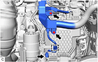
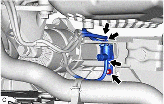
Install the vacuum switching valve (for active control engine mount
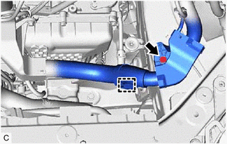
system) to the front engine mounting insulator with the nut. Torque: 6.0 N·m {61 kgf·cm, 53 in·lbf} (b) Connect the 3 vacuum hoses to the vacuum switching valve (for active control engine mount system). (c) Engage the wire harness clamp and connect the vacuum switching valve (for active control engine mount system) connector. (d) Install the 2 bolts. Torque: 10 N·m {102 kgf·cm, 7 ft·lbf} (e) Engage the wire harness clamp and install the engine wire with the bolt. Torque: 8.0 N·m {82 kgf·cm, 71 in·lbf} 2. INSTALL AIR CLEANER ASSEMBLY WITH AIR CLEANER HOSE Click here 3. INSTALL INLET AIR CLEANER ASSEMBLY Click here 4. INSTALL COOL AIR INTAKE DUCT SEAL Click here REMOVAL PROCEDURE 1. REMOVE COOL AIR INTAKE DUCT SEAL Click here 2. REMOVE INLET AIR CLEANER ASSEMBLY Click here 3. REMOVE AIR CLEANER ASSEMBLY WITH AIR CLEANER HOSE Click here 4. REMOVE VACUUM SWITCHING VALVE (for Active Control Engine Mount System) (a) Remove the bolt and disengage the wire harness clamp to separate the engine wire. (b) Remove the 2 bolts. (c)
Disengage the wire harness clamp and disconnect the vacuum switching
valve (for active control engine mount system) connector. (d) Disconnect the 3 vacuum hoses from the vacuum switching valve (for active control engine mount system). (e) Remove the nut and vacuum switching valve (for active control engine mount system) from the front engine mounting insulator.Components
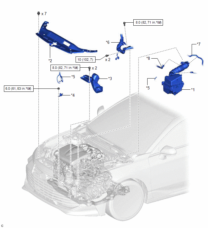

Inspection
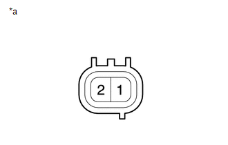
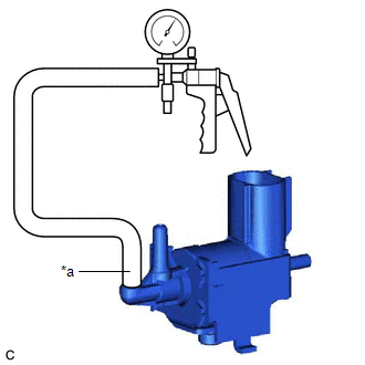
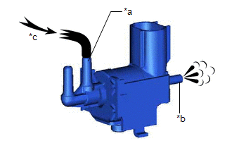
Installation


Removal


Toyota Avalon (XX50) 2019-2022 Service & Repair Manual > Smart Key System(for Start Function, Hv Model): Steering Lock Position Signal Circuit Malfunction (B2285). Engine Starter Communication Malfunction (B2779). Open / Short in Steering Lock ECU (B2781)
Steering Lock Position Signal Circuit Malfunction (B2285) DESCRIPTION This DTC is stored when the steering lock position signal sent by the steering lock ECU (steering lock actuator or upper bracket assembly) via direct line and the steering lock position signal sent via LIN communication do not mat ...