DESCRIPTION
Refer to DTC P219519.
Click here

HINT:
Although the DTC titles say O2 sensor, these DTCs relate to the air fuel ratio sensor.
|
DTC No. | Detection Item |
DTC Detection Condition | Trouble Area |
MIL | Memory |
Note |
|---|---|---|---|---|---|---|
| P223711 |
A/F (O2) Sensor Positive Current Control Bank 1 Sensor 1 Circuit Short to Ground |
The A1A+ voltage is 0.5 V or less for 5 seconds or more (2 trip detection logic). |
| Comes on |
DTC stored | SAE Code: P2238 |
|
P223712 | A/F (O2) Sensor Positive Current Control Bank 1 Sensor 1 Circuit Short to Battery |
The A1A+ voltage is higher than 4.5 V for 5 seconds or more (2 trip detection logic). |
| Comes on |
DTC stored | SAE Code: P2239 |
|
P223714 | A/F (O2) Sensor Positive Current Control Bank 1 Sensor 1 Circuit Short to Ground or Open |
An open or ground short in the circuit between terminals A1A+ and A1A- of the air fuel ratio sensor while the engine is running (2 trip detection logic). |
| Comes on |
DTC stored | SAE Code: P2237 |
|
P223716 | A/F (O2) Sensor Positive Current Control Bank 1 Sensor 1 Circuit Voltage Below Threshold |
Difference between terminals A1A+ and A1A- is 0.1 V or less for 5 seconds or more (2 trip detection logic). |
| Comes on |
DTC stored | SAE Code: P2238 |
|
P223717 | A/F (O2) Sensor Positive Current Control Bank 1 Sensor 1 Circuit Voltage Above Threshold |
Difference between terminals A1A+ and A1A- is higher than 0.8 V for 5 seconds or more (2 trip detection logic). |
| Comes on |
DTC stored | SAE Code: P2239 |
|
P22371B | A/F (O2) Sensor Positive Current Control Bank 1 Sensor 1 Circuit Resistance Above Threshold |
The air fuel ratio sensor admittance is less than 0.0054 1/Ω (2 trip detection logic). |
| Comes on |
DTC stored | SAE Code: P2238 |
|
P224011 | A/F (O2) Sensor Positive Current Control Bank 2 Sensor 1 Circuit Short to Ground |
The A2A+ voltage is 0.5 V or less for 5 seconds or more (2 trip detection logic). |
| Comes on |
DTC stored | SAE Code: P2241 |
|
P224012 | A/F (O2) Sensor Positive Current Control Bank 2 Sensor 1 Circuit Short to Battery |
The A2A+ voltage is higher than 4.5 V for 5 seconds or more (2 trip detection logic). |
| Comes on |
DTC stored | SAE Code: P2242 |
|
P224013 | A/F (O2) Sensor Positive Current Control Bank 2 Sensor 1 Circuit Open |
An open or ground short in the circuit between terminals A2A+ and A2A- of the air fuel ratio sensor while the engine is running (2 trip detection logic). |
| Comes on |
DTC stored | SAE Code: P2240 |
|
P224016 | A/F (O2) Sensor Positive Current Control Bank 2 Sensor 1 Circuit Voltage Below Threshold |
Difference between terminals A2A+ and A2A- is 0.1 V or less for 5 seconds or more (2 trip detection logic). |
| Comes on |
DTC stored | SAE Code: P2241 |
|
P224017 | A/F (O2) Sensor Positive Current Control Bank 2 Sensor 1 Circuit Voltage Above Threshold |
Difference between terminals A2A+ and A2A- is higher than 0.8 V for 5 seconds or more (2 trip detection logic). |
| Comes on |
DTC stored | SAE Code: P2242 |
|
P22401A | A/F (O2) Sensor Positive Current Control Bank 2 Sensor 1 Circuit Resistance Below Threshold |
The air fuel ratio sensor admittance is less than 0.0054 1/Ω (2 trip detection logic). |
| Comes on |
DTC stored | SAE Code: P2241 |
|
P225111 | O2 Sensor Negative Current Control Bank 1 Sensor 1 Circuit Short to Ground |
The A1A- voltage is 0.5 V or less for 5 seconds or more (2 trip detection logic). |
| Comes on |
DTC stored | SAE Code: P2252 |
|
P225112 | O2 Sensor Negative Current Control Bank 1 Sensor 1 Circuit Short to Battery |
The A1A- voltage is higher than 4.5 V for 5 seconds or more (2 trip detection logic). |
| Comes on |
DTC stored | SAE Code: P2253 |
|
P225411 | O2 Sensor Negative Current Control Bank 2 Sensor 1 Circuit Short to Ground |
The A2A- voltage is 0.5 V or less for 5 seconds or more (2 trip detection logic). |
| Comes on |
DTC stored | SAE Code: P2255 |
|
P225412 | O2 Sensor Negative Current Control Bank 2 Sensor 1 Circuit Short to Battery |
The A2A- voltage is higher than 4.5 V for 5 seconds or more (2 trip detection logic). |
| Comes on |
DTC stored | SAE Code: P2256 |
MONITOR DESCRIPTION
These DTCs are output when there is an open or short in the air fuel ratio sensor circuit, or if the air fuel ratio sensor output drops. To detect these problems, the voltage of the air fuel ratio sensor is monitored when turning the engine switch on (IG), and the admittance (admittance is an electrical term that indicates the ease of flow of current) is checked while driving. If the voltage of the air fuel ratio sensor is between 0.5 V and 4.5 V, it is considered normal. If the voltage is out of the specified range, or the admittance is less than the standard value, the ECM determines that there is a malfunction in the air fuel ratio sensor. If the same malfunction is detected in the next driving cycle, the ECM will illuminate the MIL and store a DTC.
MONITOR STRATEGY
|
Related DTCs | P2237: Air fuel ratio sensor (bank 1) open circuit between A1A+ and A1A- P2238: Air fuel ratio sensor (bank 1) low admittance P2238: Air fuel ratio sensor (bank 1) short circuit between A1A+ and GND P2238: Air fuel ratio sensor (bank 1) short circuit between A1A+ and A1A- P2239: Air fuel ratio sensor (bank 1) short circuit between A1A+ and +B P2239: Air fuel ratio sensor (bank 1) short circuit between A1A+ and A1A- P2240: Air fuel ratio sensor (bank 2) open circuit between A2A+ and A2A- P2241: Air fuel ratio sensor (bank 2) low admittance P2241: Air fuel ratio sensor (bank 2) short circuit between A2A+ and GND P2241: Air fuel ratio sensor (bank 2) short circuit between A2A+ and A2A- P2242: Air fuel ratio sensor (bank 2) short circuit between A2A+ and +B P2242: Air fuel ratio sensor (bank 2) short circuit between A2A+ and A2A- P2252: Air fuel ratio sensor (bank 1) short circuit between A1A- and GND P2253: Air fuel ratio sensor (bank 1) short circuit between A1A- and +B P2255: Air fuel ratio sensor (bank 2) short circuit between A2A- and GND P2256: Air fuel ratio sensor (bank 2) short circuit between A2A- and +B |
|
Required Sensors/Components (Main) | Air fuel ratio sensor |
|
Required Sensors/Components (Related) |
Engine coolant temperature sensor Crankshaft position sensor |
|
Frequency of Operation | Continuous |
|
Duration | 10 seconds: P2237 and P2240 10 seconds: P2238 and P2241 (air fuel ratio sensor low admittance) 5 seconds: Others |
| MIL Operation |
2 driving cycles |
| Sequence of Operation |
None |
TYPICAL ENABLING CONDITIONS
P2237, P2238, P2240 and P2241|
Monitor runs whenever the following DTCs are not stored |
P0010, P0020 (VVT oil control solenoid bank 1, 2) P0011, P0021 (VVT system bank 1, 2 - advance) P0012, P0022 (VVT system bank 1, 2 - retard) P0013, P0023 (Exhaust VVT oil control solenoid bank 1, 2) P0014, P0024 (Exhaust VVT system bank 1, 2 - advance) P0015, P0025 (Exhaust VVT system bank 1, 2 - retard) P0016, P0018 (VVT system bank 1, 2 - misalignment) P0017, P0019 (Exhaust VVT system bank 1, 2 - misalignment) P0031, P0032, P0051, P0052, P101D, P103D (Air fuel ratio sensor heater) P0037, P0038, P0057, P0058, P0141, P0161, P102D, P105D (Heated oxygen sensor heater) P0087, P0088, P0191, P0192, P0193 (Fuel pressure sensor (for high pressure side)) P0101, P0102, P0103 (Mass air flow meter) P0111, P0112, P0113 (Intake air temperature sensor) P0116, P0117, P0118 (Engine coolant temperature sensor) P011B (Engine coolant temperature/intake air temperature sensor correlation) P0121, P0122, P0123, P0222, P0223, P2135 (Throttle position sensor) P0125 (Insufficient coolant temperature for closed loop fuel control) P0128 (Thermostat) P0136, P0137, P0138, P0139, P013A, P013C, P0156, P0157, P0158, P0159, P0607 (Heated oxygen sensor) P0171, P0172, P0174, P0175 (Fuel system) P0201, P0202, P0203, P0204, P0205, P0206, P062D, P21CF, P21D0, P21D1, P21D2, P21D3, P21D4 (Fuel injector) P0300 - P0306 (Misfire) P0327, P0328, P0332, P0333 (Knock control sensor) P0335, P0337, P0338 (Crankshaft position sensor) P0340, P0342, P0343, P0345, P0347, P0348 (Camshaft position sensor) P0351 - P0356 (Igniter) P0365, P0367, P0368, P0390, P0392, P0393 (Exhaust camshaft position sensor) P0441, P00FE (EVAP system) P0500 (Vehicle speed sensor) P0657, P2102, P2103, P2111, P2112, P2119 (Throttle actuator) P107B, P107C, P107D (Fuel pressure sensor (for low pressure side)) P11EA, P11EB, P11EC, P11ED, P11EE, P11EF, P11F0, P11F1, P219A, P219B, P219C, P219D, P219E, P219F, P21A0, P21A1 (Air-fuel ratio imbalance) P1235 (High pressure fuel pump circuit) |
|
Monitor runs whenever the following DTCs are not stored |
None |
|
Engine | Running |
| Battery voltage |
11 V or higher |
| Engine switch |
On (IG) |
| Time after engine switch is off to on (IG) |
5 seconds or more |
|
Engine coolant temperature | 5°C (41°F) or higher (varies with engine speed) |
|
Fuel cut | Not executed |
|
Battery voltage | 10.5 V or higher |
|
Engine switch | On (IG) |
| Time after engine switch is off to on (IG) |
5 seconds or more |
TYPICAL MALFUNCTION THRESHOLDS
P2237 and P2240: Open Circuit Between A1A+ and A1A- / A2A+ and A2A-|
Air fuel ratio sensor admittance | Less than 0.0018 1/Ω |
|
Air fuel ratio sensor admittance | Less than 0.0053 1/Ω |
|
A1A+ / A2A+ terminal voltage | 0.5 V or less |
|
Difference between A1A+ and A1A- / A2A+ and A2A- terminal voltage |
0.1 V or less |
|
A1A+ / A2A+ terminal voltage | Higher than 4.5 V |
|
Difference between A1A+ and A1A- / A2A+ and A2A- terminal voltage |
Higher than 0.8 V |
|
A1A- / A2A- terminal voltage | 0.5 V or less |
|
A1A- / A2A- terminal voltage | Higher than 4.5 V |
CONFIRMATION DRIVING PATTERN
HINT:
Click here
Click here
HINT:
|
Techstream Display |
Description |
|---|---|
|
NORMAL |
|
|
ABNORMAL |
|
|
INCOMPLETE |
|
HINT:
The normal judgment procedure is used to complete DTC judgment and also used when clearing permanent DTCs.
WIRING DIAGRAM
Refer to DTC P219519.
Click here
CAUTION / NOTICE / HINT
NOTICE:
Inspect the fuses for circuits related to this system before performing the following procedure.
HINT:
*: The No. 1 cylinder is the cylinder which is farthest from the transaxle.
Click here
PROCEDURE
|
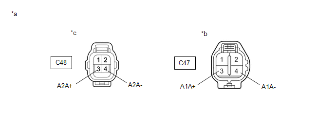
1. | CHECK TERMINAL VOLTAGE (AIR FUEL RATIO SENSOR VOLTAGE) |
|
*a | Front view of wire harness connector (to Air Fuel Ratio Sensor) |
*b | Bank 1 |
|
*c | Bank 2 |
- | - |
HINT:
Make sure that the connector is properly connected. If it is not, securely connect it and check for DTCs again.
(a) Disconnect the air fuel ratio sensor connector.
(b) Turn the engine switch on (IG).
(c) Measure the voltage according to the value(s) in the table below.
Standard Voltage:
|
Tester Connection | Condition |
Specified Condition |
|---|---|---|
|
C47-3 (A1A+) - Body ground |
Engine switch on (IG) |
3.2 to 3.4 V |
|
C47-4 (A1A-) - Body ground |
Engine switch on (IG) |
2.8 to 3.0 V |
|
C47-3 (A1A+) - C47-4 (A1A-) |
Engine switch on (IG) |
0.2 to 0.6 V |
|
C48-3 (A2A+) - Body ground |
Engine switch on (IG) |
3.2 to 3.4 V |
|
C48-4 (A2A-) - Body ground |
Engine switch on (IG) |
2.8 to 3.0 V |
|
C48-3 (A2A+) - C48-4 (A2A-) |
Engine switch on (IG) |
0.2 to 0.6 V |
HINT:
Perform "Inspection After Repair" after replacing the air fuel ratio sensor.
Click here
| OK |  | REPLACE AIR FUEL RATIO SENSOR |
|
| 2. |
CHECK HARNESS AND CONNECTOR (AIR FUEL RATIO SENSOR - ECM) |
(a) Disconnect the air fuel ratio sensor connector.
(b) Disconnect the ECM connector.
(c) Measure the resistance according to the value(s) in the table below.
Standard Resistance:
|
Tester Connection | Condition |
Specified Condition |
|---|---|---|
|
C47-1 (HA1A) - C56-52 (HA1A) |
Always | Below 1 Ω |
|
C47-3 (A1A+) - C56-125 (A1A+) |
Always | Below 1 Ω |
|
C47-4 (A1A-) - C56-126 (A1A-) |
Always | Below 1 Ω |
|
C48-1 (HA2A) - C56-17 (HA2A) |
Always | Below 1 Ω |
|
C48-3 (A2A+) - C56-123 (A2A+) |
Always | Below 1 Ω |
|
C48-4 (A2A-) - C56-124 (A2A-) |
Always | Below 1 Ω |
|
C47-1 (HA1A) or C56-52 (HA1A) - Body ground and other terminals |
Always | 10 kΩ or higher |
|
C47-3 (A1A+) or C56-125 (A1A+) - Body ground and other terminals |
Always | 10 kΩ or higher |
|
C47-4 (A1A-) or C56-126 (A1A-) - Body ground and other terminals |
Always | 10 kΩ or higher |
|
C48-1 (HA2A) or C56-17 (HA2A) - Body ground and other terminals |
Always | 10 kΩ or higher |
|
C48-3 (A2A+) or C56-123 (A2A+) - Body ground and other terminals |
Always | 10 kΩ or higher |
|
C48-4 (A2A-) or C56-124 (A2A-) - Body ground and other terminals |
Always | 10 kΩ or higher |
| OK | | REPLACE ECM |
| NG | | REPAIR OR REPLACE HARNESS OR CONNECTOR |
Toyota Avalon (XX50) 2019-2022 Service & Repair Manual > Electronically Controlled Brake System(for Hv Model): Brake Control Warning Light does not Come ON. Brake Control Warning Light Remains ON. Brake Hold Operated Indicator Light Circuit
Brake Control Warning Light does not Come ON DESCRIPTION The skid control ECU (brake booster with master cylinder assembly) is connected to the combination meter assembly via CAN communication. CAUTION / NOTICE / HINT NOTICE: After replacing the skid control ECU (brake booster with master cylinder a ...


