Throttle / Pedal Position Sensor / Switch "A" Circuit Voltage Out of Range (P01201C)
DESCRIPTION
Refer to DTC P012011.
Click here

|
DTC No. | Detection Item |
DTC Detection Condition | Trouble Area |
MIL | Memory |
Note |
| P01201C |
Throttle / Pedal Position Sensor / Switch "A" Circuit Voltage Out of Range |
The
difference between the output voltage of VTA1 and VTA2 is less than 0.8
V, or higher than 1.6 V for less than 2 seconds (1 trip detection
logic). |
- Throttle position sensor (throttle body with motor assembly)
- Throttle position sensor circuit
- ECM
| Comes on |
DTC stored | SAE Code: P0121 |
MONITOR DESCRIPTION
The
ECM uses the throttle position sensor to monitor the throttle valve
opening angle. There are several checks that the ECM performs to confirm
the proper operation of the throttle position sensor.
This
sensor transmits two signals: VTA1 and VTA2. VTA1 is used to detect the
throttle opening angle and VTA2 is used to detect malfunctions in VTA1.
The ECM performs several checks to confirm the proper operation of the
throttle position sensor and VTA1.
For each
throttle opening angle, a specific voltage difference is expected
between the outputs of VTA1 and VTA2. If the output voltage difference
between the two signals deviates from the normal operating range, the
ECM interprets this as a malfunction of the throttle position sensor,
illuminates the MIL and stores a DTC.
MONITOR STRATEGY
|
Related DTCs | P0121: Throttle position sensor rationality |
|
Required Sensors/Components (Main) | Throttle position sensor |
|
Required Sensors/Components (Related) | - |
|
Frequency of Operation | Continuous |
|
Duration | Within 2 seconds |
|
MIL Operation | Immediate |
|
Sequence of Operation | None |
TYPICAL ENABLING CONDITIONS
|
Either of the following conditions is met |
A or B |
| A. Engine switch |
On (IG) |
| B. Throttle actuator power |
On |
| Throttle position sensor circuit fail (P0122, P0123, P0222, P0223, P2135) |
Not detected |
TYPICAL MALFUNCTION THRESHOLDS
|
Either of the following conditions is met |
A or B |
| A. Difference of learned throttle position sensor opener position voltage between VTA2 and VTA1 |
Higher than 1.6 V |
| B. Difference of learned throttle position sensor opener position voltage between VTA2 and VTA1 |
Less than 0.8 V |
CONFIRMATION DRIVING PATTERN
HINT:
- After repair has been completed, clear the DTC and then check that the
vehicle has returned to normal by performing the following All Readiness
check procedure.
Click here
- When clearing the permanent DTCs, refer to the "CLEAR PERMANENT DTC" procedure.
Click here
- Connect the Techstream to the DLC3.
- Turn the engine switch on (IG).
- Turn the Techstream on.
- Clear the DTCs (even if no DTCs are stored, perform the clear DTC procedure).
- Turn the engine switch off and wait for at least 30 seconds.
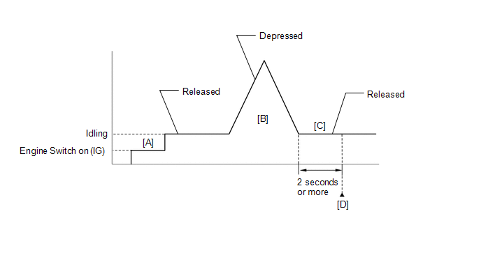
- Turn the engine switch on (IG) [A].
- Turn the Techstream on.
- Start the engine.
- With the vehicle stationary, fully depress and release the accelerator pedal [B].
- Idle the engine for 2 seconds or more [C].
- Enter the following menus: Powertrain / Engine / Trouble Codes [D].
- Read the pending DTCs.
HINT:
- If a pending DTC is output, the system is malfunctioning.
- If a pending DTC is not output, perform the following procedure.
- Enter the following menus: Powertrain / Engine / Utility / All Readiness.
- Input the DTC: P01201C.
- Check the DTC judgment result.
|
Techstream Display |
Description |
|
NORMAL |
- DTC judgment completed
- System normal
|
|
ABNORMAL |
- DTC judgment completed
- System abnormal
|
|
INCOMPLETE |
- DTC judgment not completed
- Perform driving pattern after confirming DTC enabling conditions
|
HINT:
FAIL-SAFE
When
this DTC is stored, the ECM enters fail-safe mode. During fail-safe
mode, the ECM cuts the current to the throttle actuator, and the
throttle valve is returned to a 7° throttle valve opening angle by the
return spring. The ECM then adjusts the engine output by controlling the
fuel injection (intermittent fuel-cut) and ignition timing, in
accordance with the accelerator pedal angle, to allow the vehicle to
continue running at a minimal speed. If the accelerator pedal is
depressed firmly and gently, the vehicle can be driven slowly.
Fail-safe mode continues until a pass condition is detected, and the engine switch is turned off.
WIRING DIAGRAM
Refer to DTC P012011.
Click here
CAUTION / NOTICE / HINT
HINT:
- DTC P01201C is stored when the VTA1 and VTA2 output voltages are not
consistent with the sensor characteristics. Therefore, check the Freeze
Frame Data for this DTC. Use the following formula to confirm the
relative differences in voltage.
Characteristic Sensor Output:
VTA2 x 0.8 is approximately equal to VTA1 + 1.11 V
VTA1: Throttle Position Sensor No.1 Voltage
VTA2: Throttle Position Sensor No.2 Voltage
- Read Freeze Frame Data using the Techstream. The ECM records vehicle and
driving condition information as Freeze Frame Data the moment a DTC is
stored. When troubleshooting, Freeze Frame Data can help determine if
the vehicle was moving or stationary, if the engine was warmed up or
not, if the air fuel ratio was lean or rich, and other data from the
time the malfunction occurred.
PROCEDURE
|
1. | CHECK HARNESS AND CONNECTOR (THROTTLE POSITION SENSOR - ECM) |
(a) Disconnect the throttle body with motor assembly connector.
(b) Disconnect the ECM connector.
(c) Measure the resistance according to the value(s) in the table below.
Standard Resistance:
|
Tester Connection | Condition |
Specified Condition |
|
C24-5 (VC) - C56-121 (VCTA) |
Always | Below 1 Ω |
|
C24-6 (VTA) - C56-122 (VTA1) |
Always | Below 1 Ω |
|
C24-4 (VTA2) - C56-89 (VTA2) |
Always | Below 1 Ω |
|
C24-3 (E2) - C56-120 (ETA) |
Always | Below 1 Ω |
|
C24-5 (VC) or C56-121 (VCTA) - Body ground and other terminals |
Always | 10 kΩ or higher |
|
C24-6 (VTA) or C56-122 (VTA1) - Body ground and other terminals |
Always | 10 kΩ or higher |
|
C24-4 (VTA2) or C56-89 (VTA2) - Body ground and other terminals |
Always | 10 kΩ or higher |
(d) Inspect the condition of the terminals of the connectors.
Click here
| OK |  |
GO TO STEP 5 |
|
NG |
 | |
| 2. |
REPAIR OR REPLACE HARNESS OR CONNECTOR |
(a) Repair or replace the wire harness or connector.
|
NEXT | |
| |
(a) Connect the Techstream to the DLC3.
(b) Turn the engine switch on (IG).
(c) Turn the Techstream on.
(d) Clear the DTCs.
Powertrain > Engine > Clear DTCs (e) Turn the engine switch off and wait for at least 30 seconds.
|
NEXT | |
| |
| 4. |
CHECK WHETHER DTC OUTPUT RECURS (DTC P01201C) |
(a) Drive the vehicle in accordance with the driving pattern described in Confirmation Driving Pattern.
(b) Enter the following menus: Powertrain / Engine / Trouble Codes.
(c) Read the DTCs.
Powertrain > Engine > Trouble Codes
|
Result | Proceed to |
|
DTCs are not output | A |
|
DTC P01201C is output |
B |
| A |
| END |
|
B | |
| |
| 5. |
CHECK HARNESS AND CONNECTOR (RESISTANCE OF ECM) |
(a) Disconnect the throttle body with motor assembly connector.
(b) Measure the resistance according to the value(s) in the table below.
Standard Resistance:
|
Tester Connection | Condition |
Specified Condition |
|
C24-5 (VC) - C24-6 (VTA) |
Engine switch off | 190 to 210 kΩ |
|
C24-5 (VC) - C24-4 (VTA2) |
Engine switch off | 190 to 210 kΩ |
HINT:
Perform "Inspection After Repair" after replacing the throttle body with motor assembly.
Click here
| OK |
| REPLACE THROTTLE WITH MOTOR BODY ASSEMBLY |
| NG |
| REPLACE ECM |
Camshaft Position "B" - Actuator Bank 1 Circuit Open (P001313,P002313)
DESCRIPTION
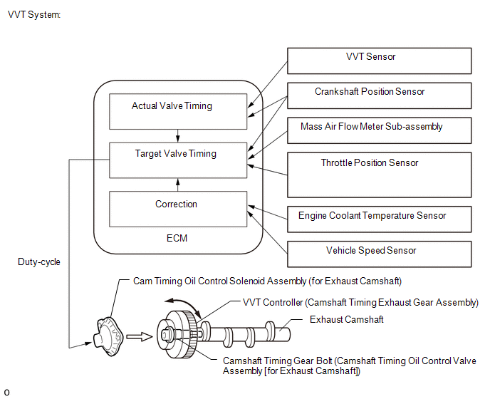
The Variable
Valve Timing (VVT) system adjusts the exhaust valve timing to improve
driveability. The engine oil pressure turns the VVT controller to adjust
the valve timing.
The cam timing oil control
solenoid assembly operates according to signals received from the ECM to
control the position of the camshaft timing oil control valve assembly
and supply engine oil. The camshaft timing oil control valve assembly
moves when the ECM applies 12 V to the cam timing oil control solenoid
assembly. The ECM changes the energizing time of the cam timing oil
control solenoid assembly (duty-cycle)in accordance with the camshaft
position, crankshaft position, throttle position, etc.
|
DTC No. | Detection Item |
DTC Detection Condition | Trouble Area |
MIL | Memory |
Note |
| P001313 |
Camshaft Position "B" - Actuator Bank 1 Circuit Open |
Open or short in cam timing oil control solenoid assembly (for exhaust camshaft of bank 1) circuit (1 trip detection logic). |
- Open or short in cam timing oil control solenoid assembly (for exhaust camshaft of bank 1) circuit
- Cam timing oil control solenoid assembly (for exhaust camshaft of bank 1)
- ECM
| Comes on |
DTC stored | SAE Code: P0013 |
|
P002313 | Camshaft Position "B" - Actuator Bank 2 Circuit Open |
Open or short in cam timing oil control solenoid assembly (for exhaust camshaft of bank 2) circuit (1 trip detection logic). |
- Open or short in cam timing oil control solenoid assembly (for exhaust camshaft of bank 2) circuit
- Cam timing oil control solenoid assembly (for exhaust camshaft of bank 2)
- ECM
| Comes on |
DTC stored | SAE Code: P0023 |
MONITOR DESCRIPTION
This
DTC is designed to detect an open or short in the cam timing oil
control solenoid assembly (for exhaust camshaft) circuit. If the cam
timing oil control solenoid duty-cycle is excessively high or low while
the engine switch is on (IG) or the engine is running, the ECM will
illuminate the MIL and store this DTC.
MONITOR STRATEGY
|
Related DTCs | P0013: Cam timing oil control solenoid assembly (for exhaust camshaft of bank 1) range check
P0023: Cam timing oil control solenoid assembly (for exhaust camshaft of bank 2) range check |
|
Required Sensors/Components (Main) | Cam timing oil control solenoid assembly (for exhaust camshaft) |
|
Required Sensors/Components (Related) | - |
|
Frequency of Operation | Continuous |
|
Duration | 1 second |
| MIL Operation |
Immediate |
| Sequence of Operation |
None |
TYPICAL ENABLING CONDITIONS
All |
Monitor runs whenever the following DTCs are not stored |
None |
| All of the following conditions are met |
- |
| Battery voltage | 8 V or higher |
|
Starter | Off |
|
Engine switch | On (IG) |
|
Time after engine switch off to on (IG) |
0.5 seconds or more |
Case 1 |
Either of the following conditions is met |
A or B |
| A. Both of the following conditions are met |
- |
| Battery voltage |
11 V or higher, and less than 13 V |
|
Target duty cycle | Less than 70% |
|
B. Both of the following conditions are met |
- |
| Battery voltage | 13 V or higher |
|
Target duty cycle | Less than 80% |
Case 2 |
Both of the following conditions are met | - |
|
Current cut status | Not cut |
|
Target duty cycle | 25% or higher |
TYPICAL MALFUNCTION THRESHOLDS
Case 1 |
Output duty cycle | 100% or higher |
Case 2 |
Output duty cycle | 0% or less |
CONFIRMATION DRIVING PATTERN
HINT:
- After repair has been completed, clear the DTC and then check that the
vehicle has returned to normal by performing the following All Readiness
check procedure.
Click here 
- When clearing the permanent DTCs, refer to the "CLEAR PERMANENT DTC" procedure.
Click here
- Connect the Techstream to the DLC3.
- Turn the engine switch on (IG).
- Turn the Techstream on.
- Clear the DTCs (even if no DTCs are stored, perform the clear DTC procedure).
- Turn the engine switch off and wait for at least 30 seconds.
- Start the engine [A].
- Wait 5 seconds or more [B].
- Turn the Techstream on.
- Enter the following menus: Powertrain / Engine / Trouble Codes [C].
- Read the pending DTCs.
HINT:
- If a pending DTC is output, the system is malfunctioning.
- If a pending DTC is not output, perform the following procedure.
- Enter the following menus: Powertrain / Engine / Utility / All Readiness.
- Input the DTC: P001313 or P002313.
- Check the DTC judgment result.
|
Techstream Display |
Description |
|
NORMAL |
- DTC judgment completed
- System normal
|
|
ABNORMAL |
- DTC judgment completed
- System abnormal
|
|
INCOMPLETE |
- DTC judgment not completed
- Perform driving pattern after confirming DTC enabling conditions
|
HINT:
WIRING DIAGRAM
CAUTION / NOTICE / HINT
HINT:
PROCEDURE
(a) Connect the Techstream to the DLC3.
(b) Turn the engine switch on (IG).
(c) Turn the Techstream on.
(d) Clear the DTC after recording the Freeze Frame Data and DTC.
Powertrain > Engine > Clear DTCs
(e) Turn the engine switch off and wait for at least 30 seconds.
|
NEXT |
 | |
| 2. |
READ OUTPUT DTC (DTC P001313 OR P002313) |
(a) Connect the Techstream to the DLC3.
(b) Start the engine.
(c) Turn the Techstream on.
(d) Enter the following menus: Powertrain / Engine / Trouble Codes.
(e) Read the DTCs.
Powertrain > Engine > Trouble Codes
|
Result | Proceed to |
|
DTC P001313 or P002313 is output |
A |
| DTCs are not output |
B |
| B |
 | CHECK FOR INTERMITTENT PROBLEMS |
|
A | |
| |
| 3. |
INSPECT CAM TIMING OIL CONTROL SOLENOID ASSEMBLY (FOR EXHAUST CAMSHAFT) |
(a) Inspect the cam timing oil control solenoid assembly (for exhaust camshaft).
Click here
| NG |
| REPLACE CAM TIMING OIL CONTROL SOLENOID ASSEMBLY (FOR EXHAUST CAMSHAFT) |
|
OK | |
| |
| 4. |
CHECK HARNESS AND CONNECTOR (CAM TIMING OIL CONTROL SOLENOID ASSEMBLY (FOR EXHAUST CAMSHAFT) - ECM) |
(a) Disconnect the cam timing oil control solenoid assembly (for exhaust camshaft) connector.
(b) Disconnect the ECM connector.
(c) Measure the resistance according to the value(s) in the table below.
Standard Resistance:
|
Tester Connection | Condition |
Specified Condition |
|
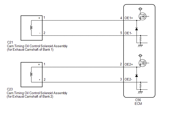
C21-1 (+) - C56-4 (OE1+) |
Always | Below 1 Ω |
|
C21-2 (-) - C56-5 (OE1-) |
Always | Below 1 Ω |
|
C23-1 (+) - C56-2 (OE2+) |
Always | Below 1 Ω |
|
C23-2 (-) - C56-3 (OE2-) |
Always | Below 1 Ω |
|
C21-1 (+) or C56-4 (OE1+) - Body ground and other terminals |
Always | 10 kΩ or higher |
|
C21-2 (-) or C56-5 (OE1-) - Body ground and other terminals |
Always | 10 kΩ or higher |
|
C23-1 (+) or C56-2 (OE2+) - Body ground and other terminals |
Always | 10 kΩ or higher |
|
C23-2 (-) or C56-3 (OE2-) - Body ground and other terminals |
Always | 10 kΩ or higher |
| OK |
| REPLACE ECM |
| NG |
| REPAIR OR REPLACE HARNESS OR CONNECTOR |
Camshaft Position "B" - Timing Over-Advanced or System Performance Bank 1 (P001400,P001500,P002400,P002500)
DESCRIPTION
Refer to DTC P001313.
Click here

|
DTC No. | Detection Item |
DTC Detection Condition | Trouble Area |
MIL | Memory |
Note |
| P001400 |
Camshaft Position "B" - Timing Over-Advanced or System Performance Bank 1 |
Exhaust valve timing is stuck at a certain value when in the advance range (2 trip detection logic). |
- Valve timing
- Cam timing oil control solenoid assembly (for exhaust camshaft of bank 1)
- Camshaft timing gear bolt (camshaft timing oil control valve assembly [for exhaust camshaft of bank 1])
- Camshaft timing exhaust gear assembly (bank 1)
- Oil control valve filter (for exhaust camshaft of bank 1)
- ECM
| Comes on |
DTC stored | SAE Code: P0014 |
|
P001500 | Camshaft Position "B" - Timing Over-Retarded Bank 1 |
Exhaust valve timing is stuck at a certain value when in the retard range (1 trip detection logic). |
- Valve timing
- Cam timing oil control solenoid assembly (for exhaust camshaft of bank 1)
- Camshaft timing gear bolt (camshaft timing oil control valve assembly [for exhaust camshaft of bank 1])
- Camshaft timing exhaust gear assembly (bank 1)
- Oil control valve filter (for exhaust camshaft of bank 1)
- ECM
| Comes on |
DTC stored | SAE Code: P0015 |
|
P002400 | Camshaft Position "B" - Timing Over-Advanced or System Performance Bank 2 |
Exhaust valve timing is stuck at a certain value when in the advance range (2 trip detection logic). |
- Valve timing
- Cam timing oil control solenoid assembly (for exhaust camshaft of bank 2)
- Camshaft timing gear bolt (camshaft timing oil control valve assembly [for exhaust camshaft of bank 2])
- Camshaft timing exhaust gear assembly (bank 2)
- Oil control valve filter (for exhaust camshaft of bank 2)
- ECM
| Comes on |
DTC stored | SAE Code: P0024 |
|
P002500 | Camshaft Position "B" - Timing Over-Retarded Bank 2 |
Exhaust valve timing is stuck at a certain value when in the retard range (1 trip detection logic). |
- Valve timing
- Cam timing oil control solenoid assembly (for exhaust camshaft of bank 2)
- Camshaft timing gear bolt (camshaft timing oil control valve assembly [for exhaust camshaft of bank 2])
- Camshaft timing exhaust gear assembly (bank 2)
- Oil control valve filter (for exhaust camshaft of bank 2)
- ECM
| Comes on |
DTC stored | SAE Code: P0025 |
MONITOR DESCRIPTION
The
ECM optimizes the exhaust valve timing using the Variable Valve Timing
(VVT) system to control the exhaust camshaft. The VVT system includes
the ECM, cam timing oil control solenoid assembly, camshaft timing gear
bolt (camshaft timing oil control valve assembly [for exhaust camshaft])
and camshaft timing exhaust gear assembly. The ECM sends a target
duty-cycle control signal to the cam timing oil control solenoid
assembly. The camshaft timing gear bolt (camshaft timing oil control
valve assembly [for exhaust camshaft]) is operated to control the oil
pressure supplied to the camshaft timing exhaust gear assembly based on
this signal. The camshaft timing exhaust gear assembly can advance or
retard the exhaust camshaft.
If the difference
between the target and actual exhaust valve timing is large, and changes
in the actual exhaust valve timing are small, the ECM interprets this
as the camshaft timing exhaust gear assembly stuck malfunction and
stores a DTC.
- Example:
- A DTC is stored when the following conditions are met:
- It takes 5 seconds or more to change the valve timing by 5°CA.
- After the above condition is met, the cam timing oil control solenoid is forcibly activated for 9.5 seconds.
DTC P001400 and P002400 (Advanced Camshaft Timing) is subject to 2 trip detection logic.
DTC P001500 and P002500 (Retarded Camshaft Timing) is subject to 1 trip detection logic.
These
DTCs indicate that the camshaft timing exhaust gear assembly cannot
operate properly due to a camshaft timing gear bolt (camshaft timing oil
control valve assembly [for exhaust camshaft]) malfunction or the
presence of foreign matter in the camshaft timing gear bolt (camshaft
timing oil control valve assembly [for exhaust camshaft]).
MONITOR STRATEGY
|
Related DTCs | P0014: Advanced camshaft timing (for exhaust camshaft of bank 1)
P0015: Retarded camshaft timing (for exhaust camshaft of bank 1) P0024: Advanced camshaft timing (for exhaust camshaft of bank 2)
P0025: Retarded camshaft timing (for exhaust camshaft of bank 2) |
|
Required Sensors/Components (Main) | Cam timing oil control solenoid assembly (for exhaust camshaft)
Camshaft timing gear bolt (camshaft timing oil control valve assembly [for exhaust camshaft])
Camshaft timing exhaust gear assembly |
|
Required Sensors/Components (Related) |
Crankshaft position sensor VVT sensor Engine coolant temperature sensor |
|
Frequency of Operation | Continuous |
|
Duration | Within 10 seconds |
|
MIL Operation | Advanced camshaft timing: 2 driving cycles
Retarded camshaft timing: Immediate |
|
Sequence of Operation | None |
TYPICAL ENABLING CONDITIONS
|
Monitor runs whenever the following DTCs are not stored |
P0013, P0023 (Exhaust VVT oil control solenoid bank1, 2) P0017, P0019 (Exhaust VVT system bank1, 2 - misalignment)
P0101, P0102, P0103 (Mass air flow meter) P0117, P0118 (Engine coolant temperature sensor)
P0125 (Insufficient coolant temperature for closed loop fuel control)
P0335, P0337, P0338 (Crankshaft position sensor) P0340, P0342, P0343, P0345, P0347, P0348 (Camshaft position sensor)
P0365, P0367, P0368, P0390, P0392, P0393 (Exhaust camshaft position sensor) |
|
Battery voltage | 11 V or higher |
|
Engine speed | 500 to 4000 rpm |
|
Engine coolant temperature | 75 to 100°C (167 to 212°F) |
TYPICAL MALFUNCTION THRESHOLDS
P0014 and P0024: Advanced Camshaft Timing |
Both of the following conditions are met |
- |
| Deviation of actual valve timing and target valve timing |
More
than 5°CA (Crankshaft Angle) for 5 seconds or more after the VVT hold
duty ratio learned value reaches the upper or lower limit. |
|
Valve timing | No change at advanced valve timing |
P0015 and P0025: Retarded Camshaft Timing |
Both of the following conditions are met |
- |
| Deviation of actual valve timing and target valve timing |
More
than 5°CA (Crankshaft Angle) for 5 seconds or more after the VVT hold
duty ratio learned value reaches the upper or lower limit. |
|
Valve timing | No change at retarded valve timing |
If
the difference between the target and actual camshaft timing is greater
than the specified value, the ECM operates the VVT actuator for 10
seconds by applying and releasing oil pressure. Then, the ECM monitors
the camshaft timing change for 10 seconds.
MONITOR RESULT
Refer to detailed information in Checking Monitor Status.
Click here
P0014, P0015: Exhaust Gas Recirculation/VVT / EX VVT STUCK B1 |
Monitor ID | Test ID |
Scaling | Unit |
Description |
| $35 |
$85 | Multiply by 0.01 |
Second | Forced movement of cam timing control actuator time |
P0024, P0025: Exhaust Gas Recirculation/VVT / EX VVT STUCK B2 |
Monitor ID | Test ID |
Scaling | Unit |
Description |
| $36 |
$85 | Multiply by 0.01 |
Second | Forced movement of cam timing control actuator time |
CONFIRMATION DRIVING PATTERN
HINT:
- After repair has been completed, clear the DTC and then check that the
vehicle has returned to normal by performing the following All Readiness
check procedure.
Click here
- When clearing the permanent DTCs, refer to the "CLEAR PERMANENT DTC" procedure.
Click here
- Connect the Techstream to the DLC3.
- Turn the engine switch on (IG).
- Turn the Techstream on.
- Clear the DTCs (even if no DTCs are stored, perform the clear DTC procedure).
- Turn the engine switch off and wait for at least 30 seconds.
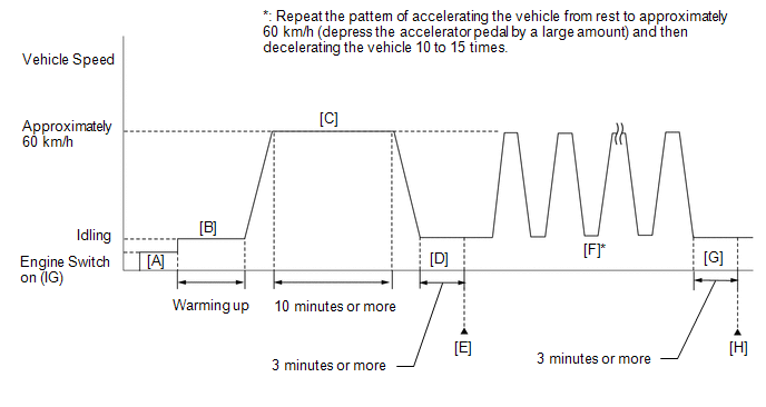
- Turn the engine switch on (IG) [A].
- Turn the Techstream on.
- Start the engine and warm it up until the engine coolant temperature reaches 75°C (167°F) or higher [B].
- Drive the vehicle at approximately 60 km/h (37 mph) for 10 minutes or more [C].
CAUTION:
When performing the confirmation driving pattern, obey all speed limits and traffic laws.
- Idle the engine for 3 minutes or more [D].
- Enter the following menus: Powertrain / Engine / Trouble Codes [E].
- Read the pending DTCs.
HINT:
- If a pending DTC is output, the system is malfunctioning.
- If a pending DTC is not output, perform the following procedure.
- Enter the following menus: Powertrain / Engine / Utility / All Readiness.
- Input the DTC: P001400, P001500, P002400 or P002500.
- Check the DTC judgment result.
|
Techstream Display |
Description |
|
NORMAL |
- DTC judgment completed
- System normal
|
|
ABNORMAL |
- DTC judgment completed
- System abnormal
|
|
INCOMPLETE |
- DTC judgment not completed
- Perform driving pattern after confirming DTC enabling conditions
|
HINT:
- Repeat the pattern of accelerating the vehicle from rest to
approximately 60 km/h (37 mph) and then decelerating the vehicle 10 to
15 times [F].
CAUTION:
When performing the confirmation driving pattern, obey all speed limits and traffic laws.
HINT:
Depress the accelerator pedal by a large amount.
- Idle the engine for 3 minutes or more [G].
- Enter the following menus: Powertrain / Engine / Trouble Codes [H].
- Read the pending DTCs.
HINT:
- If a pending DTC is output, the system is malfunctioning.
- If a pending DTC is not output, perform the following procedure.
- Check the DTC judgment result again.
HINT:
WIRING DIAGRAM
Refer to DTC P001313.
Click here
CAUTION / NOTICE / HINT
|
Abnormal Bank | Timing Over Advanced
(Valve timing is out of specified range) |
Timing Over Retarded (Valve timing is out of specified range) |
|
Bank 1 | P001400 |
P001500 |
| Bank 2 |
P002400 | P002500 |
PROCEDURE
|
1. | CHECK ANY OTHER DTCS OUTPUT (IN ADDITION TO DTC P001400, P001500, P002400 OR P002500) |
(a) Connect the Techstream to the DLC3.
(b) Turn the engine switch on (IG).
(c) Turn the Techstream on.
(d) Enter the following menus: Powertrain / Engine / Trouble Codes.
(e) Read the DTCs.
Powertrain > Engine > Trouble Codes
|
Result | Proceed to |
|
DTC P001400, P001500, P002400 or P002500 is output |
A |
| DTC P001400, P001500, P002400 or P002500 and other DTCs are output |
B |
HINT:
If any DTCs other than P001400, P001500, P002400 or P002500 are output, troubleshoot those DTCs first.
| B |
 | GO TO DTC CHART |
|
A |
 | |
| 2. |
PERFORM ACTIVE TEST USING TECHSTREAM (CONTROL THE EXHAUST VVT OCV DUTY RATIO) |
(a) Connect the Techstream to the DLC3.
(b) Start the engine.
(c) Turn the Techstream on.
(d)
Enter the following menus: Powertrain / Engine / Active Test / Control
the Exhaust VVT OCV Duty Ratio Bank 1 or Control the Exhaust VVT OCV
Duty Ratio Bank 2.
Powertrain > Engine > Active Test
|
Tester Display |
| Control the Exhaust VVT OCV Duty Ratio Bank 1 |
Powertrain > Engine > Active Test
|
Tester Display |
| Control the Exhaust VVT OCV Duty Ratio Bank 2 |
(e)
Check the engine speed while operating the cam timing oil control
solenoid assembly (for exhaust camshaft) using the Techstream.
OK:
|
Techstream Operation | Engine Condition |
|
0% | Normal engine speed |
|
100% | Engine idles roughly or stalls |
HINT:
Refer
to "Data List / Active Test" [Exhaust VVT OCV Control Duty Ratio Bank
1, Exhaust VVT Change Angle Bank 1, Exhaust VVT OCV Control Duty Ratio
Bank 2 and Exhaust VVT Change Angle Bank 2].
Click here
| NG | |
GO TO STEP 4 |
|
OK | |
| |
| 3. |
CHECK WHETHER DTC OUTPUT RECURS (DTC P001400, P001500, P002400 OR P002500) |
(a) Connect the Techstream to the DLC3.
(b) Turn the engine switch on (IG).
(c) Turn the Techstream on.
(d) Clear the DTCs.
Powertrain > Engine > Clear DTCs
(e) Turn the engine switch off and wait for at least 30 seconds.
(f) Turn the engine switch on (IG).
(g) Turn the Techstream on.
(h) Start the engine and warm it up.
(i) Drive the vehicle in accordance with the driving pattern described in Confirmation Driving Pattern.
(j) Enter the following menus: Powertrain / Engine / Trouble Codes.
(k) Read the DTCs.
Powertrain > Engine > Trouble Codes
|
Result | Proceed to |
|
DTCs are not output | A |
|
DTC P001400, P001500, P002400 or P002500 is output |
B |
HINT:
DTC
P001400, P001500, P002400 or P002500 may be stored when foreign matter
in the engine oil is caught in some parts of the system. The DTC will
remain stored even if the system returns to normal after a short time.
This foreign matter may then be captured by the oil filter.
| A |
| CHECK FOR INTERMITTENT PROBLEMS |
|
B | |
| |
| 4. |
INSPECT CAM TIMING OIL CONTROL SOLENOID ASSEMBLY (FOR EXHAUST CAMSHAFT) |
(a) Inspect the cam timing oil control solenoid assembly (for exhaust camshaft).
Click here
| NG |
| GO TO STEP 10 |
|
OK | |
| |
| 5. |
INSPECT CAMSHAFT TIMING GEAR BOLT (CAMSHAFT TIMING OIL CONTROL VALVE ASSEMBLY [FOR EXHAUST CAMSHAFT]) |
(a) Inspect the camshaft timing gear bolt (camshaft timing oil control valve assembly [for exhaust camshaft]).
- for Bank 1: Click here
- for Bank 2: Click here
| NG |
| GO TO STEP 12 |
|
OK | |
| |
| 6. |
CHECK VALVE TIMING (CHECK FOR LOOSE TIMING CHAIN AND JUMPED TEETH) |
(a) Remove the cylinder head cover sub-assembly and cylinder head cover sub-assembly LH.
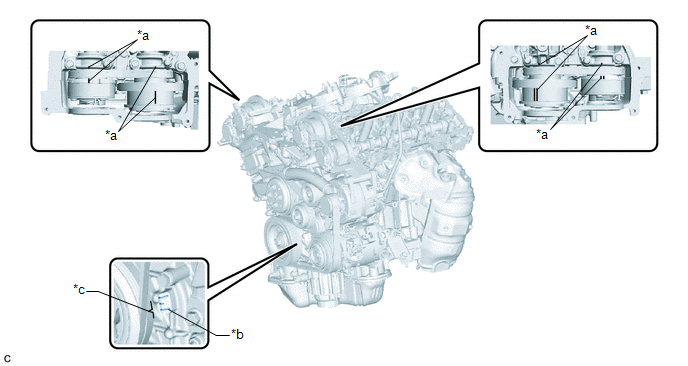
|
*a | Timing Mark |
*b | TDC Timing Mark |
|
*c | Groove |
- | - |
(b) Turn the crankshaft pulley and align its groove with the TDC timing mark of the timing chain cover.
(c)
Check that the timing marks of the camshaft timing gear assemblies and
camshaft timing exhaust gear assemblies are aligned with the timing
marks of the bearing cap as shown in the illustration.
HINT:
If the timing marks are not as shown, turn the crankshaft one revolution clockwise.
OK:
Timing
marks on camshaft timing gear assemblies and camshaft timing exhaust
gear assemblies are aligned as shown in the illustration.
HINT:
If
the result is not as specified, check for mechanical malfunctions that
may have affected the valve timing, such as a jumped tooth or stretching
of the timing chain.
| NG | |
GO TO STEP 8 |
|
OK | |
| |
| 7. |
INSPECT OIL CONTROL VALVE FILTER (FOR EXHAUST CAMSHAFT) |
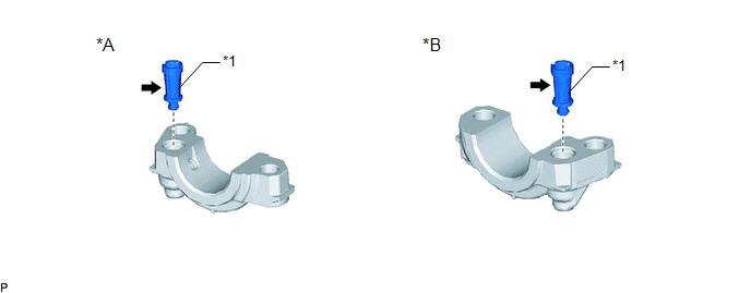
|
*A | for Exhaust Camshaft of Bank 1 |
*B | for Exhaust Camshaft of Bank 2 |
|
*1 | Oil Control Valve Filter |
- | - |
(a)
Remove the oil control valve filter (for exhaust camshaft of bank 1) or
oil control valve filter (for exhaust camshaft of bank 2).
- for Bank 1: Click here
- for Bank 2: Click here
(b) Check that the filter is not clogged.
OK:
Filter is not clogged.
| OK |
| GO TO STEP 14 |
| NG |
| REPLACE OIL CONTROL VALVE FILTER (FOR EXHAUST CAMSHAFT) |
| 8. |
CHECK ENGINE MECHANICAL SYSTEM |
(a) Check for mechanical malfunctions that affect the valve timing, such as a jumped tooth or stretching of the timing chain.
HINT:
Perform "Inspection After Repair" after repairing or replacing the engine mechanical system.
Click here
| NG |
| REPAIR OR REPLACE MALFUNCTIONING PARTS, COMPONENT AND AREA |
|
OK | |
| |
| 9. |
CHECK WHETHER DTC OUTPUT RECURS (DTC P001400, P001500, P002400 OR P002500) |
(a) Connect the Techstream to the DLC3.
(b) Turn the engine switch on (IG).
(c) Turn the Techstream on.
(d) Clear the DTCs.
Powertrain > Engine > Clear DTCs
(e) Turn the engine switch off and wait for at least 30 seconds.
(f) Turn the engine switch on (IG).
(g) Turn the Techstream on.
(h) Start the engine and warm it up.
(i) Drive the vehicle in accordance with the driving pattern described in Confirmation Driving Pattern.
(j) Enter the following menus: Powertrain / Engine / Trouble Codes.
(k) Read the DTCs.
Powertrain > Engine > Trouble Codes
|
Result | Proceed to |
|
DTCs are not output | A |
|
DTC P001400, P001500, P002400 or P002500 is output |
B |
| A |
| CHECK FOR INTERMITTENT PROBLEMS |
| B |
| REPLACE ECM |
| 10. |
REPLACE CAM TIMING OIL CONTROL SOLENOID ASSEMBLY (FOR EXHAUST CAMSHAFT) |
(a) Replace the cam timing oil control solenoid assembly (for exhaust camshaft).
Click here
|
NEXT | |
| |
| 11. |
INSPECT CAMSHAFT TIMING GEAR BOLT (CAMSHAFT TIMING OIL CONTROL VALVE ASSEMBLY [FOR EXHAUST CAMSHAFT]) |
(a) Inspect the camshaft timing gear bolt (camshaft timing oil control valve assembly [for exhaust camshaft]).
- for Bank 1: Click here
- for Bank 2: Click here
| OK |
| GO TO STEP 13 |
|
NG | |
| |
| 12. |
REPLACE CAMSHAFT TIMING GEAR BOLT (CAMSHAFT TIMING OIL CONTROL VALVE ASSEMBLY [FOR EXHAUST CAMSHAFT]) |
(a) Replace the camshaft timing gear bolt (camshaft timing oil control valve assembly [for exhaust camshaft]).
- for Bank 1: Click here
- for Bank 2: Click here
|
NEXT | |
| |
| 13. |
PERFORM ACTIVE TEST USING TECHSTREAM (CONTROL THE EXHAUST VVT OCV DUTY RATIO) |
(a) Connect the Techstream to the DLC3.
(b) Start the engine.
(c) Turn the Techstream on.
(d)
Enter the following menus: Powertrain / Engine / Active Test / Control
the Exhaust VVT OCV Duty Ratio Bank 1 or Control the Exhaust VVT OCV
Duty Ratio Bank 2.
Powertrain > Engine > Active Test
|
Tester Display |
| Control the Exhaust VVT OCV Duty Ratio Bank 1 |
Powertrain > Engine > Active Test
|
Tester Display |
| Control the Exhaust VVT OCV Duty Ratio Bank 2 |
(e)
Check the engine speed while operating the cam timing oil control
solenoid assembly (for exhaust camshaft) using the Techstream.
OK:
|
Techstream Operation | Engine Condition |
|
0% | Normal engine speed |
|
100% | Engine idles roughly or stalls |
HINT:
Refer
to "Data List / Active Test" [Exhaust VVT OCV Control Duty Ratio Bank
1, Exhaust VVT Change Angle Bank 1, Exhaust VVT OCV Control Duty Ratio
Bank 2 and Exhaust VVT Change Angle Bank 2].
Click here
| OK | |
END |
|
NG | |
| |
| 14. |
REPLACE CAMSHAFT TIMING EXHAUST GEAR ASSEMBLY |
(a) Replace the camshaft timing exhaust gear assembly.
Click here
HINT:
Perform "Inspection After Repair" after replacing the camshaft timing exhaust gear assembly.
Click here
|
NEXT | |
| |
| 15. |
CHECK WHETHER DTC OUTPUT RECURS (DTC P001400, P001500, P002400 OR P002500) |
(a) Connect the Techstream to the DLC3.
(b) Turn the engine switch on (IG).
(c) Turn the Techstream on.
(d) Clear the DTCs.
Powertrain > Engine > Clear DTCs
(e) Turn the engine switch off and wait for at least 30 seconds.
(f) Turn the engine switch on (IG).
(g) Turn the Techstream on.
(h) Start the engine and warm it up.
(i) Drive the vehicle in accordance with the driving pattern described in Confirmation Driving Pattern.
(j) Enter the following menus: Powertrain / Engine / Trouble Codes.
(k) Read the DTCs.
Powertrain > Engine > Trouble Codes
|
Result | Proceed to |
|
DTCs are not output | A |
|
DTC P001400, P001500, P002400 or P002500 is output |
B |
| A |
| END |
| B |
| REPLACE ECM |


