FAIL-SAFE CHART If any of
the following DTCs are stored, the ECM enters fail-safe mode to allow
the vehicle to be driven temporarily or stops fuel injection. DTC Code Component Fail-Safe Operation Fail-Safe Deactivation Condition P001100 P001107 P001500 P002100 P002107 P002500 VVT system Pass condition detected P003012 P003013 P005012 P005013 P101A9E P103A9E Air fuel ratio sensor heater The ECM turns off the air fuel ratio sensor heater. Engine switch off P003612 P003614 P005612 P005614 P102A9E P105A9E Heated oxygen sensor heater The ECM turns off the heated oxygen sensor heater. Engine switch off P008700 P008800 P123513 Fuel pump assembly (for high pressure side) Engine switch off P010012 P010014 Mass air flow meter sub-assembly The ECM calculates fuel injection volume according to the engine speed and throttle valve position. Pass condition detected P011011 P011015 Intake air temperature sensor The ECM estimates the intake air temperature to be 20°C (68°F). Pass condition detected and then engine switch turned off P011511 P011515 Engine coolant temperature sensor The ECM estimates the engine coolant temperature to be 80°C (176°F). Pass condition detected P012011 P012015 P01201C P022011 P022015 P060444 P060604 P060629 P060647 P060A47 P060B49 P060D49 P060E49 P061E49 P065714 P06579E P160700 P210014 P210015 P211172 P211173 P211900 P211904 P211977 P21352B Electronic throttle control system The ECM cuts off throttle actuator current and the throttle valve is returned to a 7° throttle position by the return spring. The
ECM then adjusts the engine output by controlling fuel injection
(intermittent fuel-cut) and ignition timing in accordance with the
accelerator pedal angle to allow the vehicle to be driven at a low
speed*1. Pass condition detected and then engine switch turned off P019011 P019015 Fuel pressure sensor (for high pressure) Pass condition detected and then engine switch turned off P020113 P020213 P020313 P020413 P020513 P020613 P062D13 ECM (injector driver) The ECM performs fuel-cut when the engine speed is 2500 rpm or more. Pass condition detected and then engine switch turned off P030000 P030027 P030085 P030100 P030200 P030300 P030400 P030500 P030600 *2 When a
catalyst-damaging misfire occurs (MIL blinking), the following fail-safe
operation is performed for catalyst overheat malfunction prevention. - Fuel cut is performed on the malfunctioning cylinder. - Throttle valve opening angle control is performed. - Fuel cut is performed on all cylinders or the malfunctioning cylinder. Pass condition detected and then engine switch turned off P032511 P032515 P033011 P033015 Knock control sensor The ECM sets the ignition timing to maximum retard. Engine switch off P035113 P035213 P035313 P035413 P035513 P035613 Ignition coil assembly The ECM cuts the fuel injection. Pass condition detected P05042B Stop light switch assembly The accelerator pedal opening angle is fixed when there is an accelerator pedal malfunction or history of a malfunction. Pass condition detected and then engine switch turned off P056014 ECM +B circuit Generator command is maintained. Pass condition detected and then engine switch turned off P107A11 P107A15 Fuel pressure sensor (for low pressure side) Pass condition detected and then engine switch turned off P21CF13 P21D013 P21D113 P21D213 P21D313 P21D413 Fuel injector assembly (for port injection) The ECM performs fuel-cut when the engine speed is 2500 rpm or more. Pass condition detected and then engine switch turned off P212012 P212014 P21201C P21201F P212099 P212512 P212514 P21251F P21382B Accelerator pedal position sensor The accelerator pedal position sensor has 2 sensor circuits: Main and Sub. If either circuit malfunctions, the ECM limits the engine output. If
both circuits malfunction, the ECM regards the accelerator pedal as
being released. As a result, the throttle valve is closed and the engine
idles. Pass condition detected and then engine switch turned off P223711 P223712 P223713 P223716 P223717 P22371B P224011 P224012 P224013 P224016 P224017 P22401B P225111 P225112 P225411 P225412 Air fuel ratio sensor Air fuel ratio feedback control is stopped Pass condition detected and then engine switch turned off HINT: FREEZE FRAME DATA DESCRIPTION The
ECM records vehicle and driving condition information as freeze frame
data the moment a DTC is stored. When troubleshooting, freeze frame data
can be helpful in determining whether the vehicle was moving or
stationary, whether the engine was warmed up or not, whether the air
fuel ratio was lean or rich, as well as other data recorded at the time
of a malfunction. HINT: PENDING FREEZE FRAME DATA HINT: Pending freeze frame data is stored when a 2 trip DTC is first detected during the first trip. (a) Connect the Techstream to the DLC3. (b) Turn the engine switch on (IG). (c) Turn the Techstream on. (d) Enter the following menus: Powertrain / Engine / Trouble Codes. (e) Select a DTC in order to display its pending freeze frame data. HINT: LIST OF FREEZE FRAME DATA Tester Display Total Distance Traveled Total Distance Traveled - Unit Vehicle Speed Engine Speed Calculate Load Vehicle Load Mass Air Flow Sensor Atmospheric Pressure Coolant Temperature Intake Air Temperature Ambient Temperature Engine Run Time IG-ON Coolant Temperature Initial Engine Coolant Temperature IG-ON Intake Air Temperature Initial Engine Intake Air Temperature Battery Voltage BATT Voltage Glow Indicator Supported Accelerator Position Accelerator Position Sensor No.1 Voltage % Accelerator Position Sensor No.2 Voltage % Accelerator Position Sensor No.1 Voltage Accelerator Position Sensor No.2 Voltage Accelerator Idle Position Accelerator Position Sensor No.1 Fully Closed Learn Value Accelerator Position Sensor No.2 Fully Closed Learn Value Engine Starting Torque Control Count Throttle Position Sensor No.1 Voltage % Throttle Position Sensor No.2 Voltage % System Guard Open Side Malfunction Throttle Request Position Throttle Sensor Position Throttle Position Sensor No.1 Voltage Throttle Position Sensor No.2 Voltage Throttle Position Command Throttle Position Sensor Open Position No.1 Throttle Position Sensor Open Position No.2 Throttle Motor Current Throttle Motor Duty Ratio Throttle Motor Duty Ratio (Open) Throttle Motor Duty Ratio (Close) Throttle Position Sensor Fully Closed Learn Value +BM Voltage Actuator Power Supply Throttle Air Flow Learn Value (Area 1) Throttle Air Flow Learn Value (Area 2) Throttle Air Flow Learn Value (Area 3) Throttle Air Flow Learn Value (Calculated Value) Throttle Air Flow Learn Value (Atmosphere Pressure Offset Value) Low Revolution Control N Range Status Engine Stall Control F/B Flow ISC F/B Learn Torque ISC Total AUXS Torque ISC F/B Torque Sum of ISC F/B Torque (Recent) ISC AUXS Torque (Alternator) ISC AUXS Torque (Air Conditioner) Throttle Air Flow F/B Value Throttle Position Target Fuel Pressure (High) Target Fuel Pressure (High) Supported Target Fuel Pressure (Low) Target Fuel Pressure (Low) Supported Fuel Pressure (High) Fuel Pressure (High) Supported Fuel Pressure (Low) Fuel Pressure (Low) Supported VSV for Vent Valve Vacuum Pump Fuel Pump Control Duty Ratio Injector Cylinder #1 (Port) Injection Volume Cylinder #1 Target Fuel Pressure Offset Injection Volume Low Fuel Pressure Sensor High Fuel Pressure Sensor High Pressure Fuel Pump Duty Ratio (D4) High Pressure Fuel Pump Discharge Rate Injection Mode Injection Switching Status Injection Timing Cylinder #1 (D4) Injection Time Cylinder #1 (D4) Current Fuel Type EVAP (Purge) VSV Target Air-Fuel Ratio A/F (O2) Lambda Sensor B1S1 A/F (O2) Lambda Sensor B2S1 A/F (O2) Sensor Voltage B1S1 A/F (O2) Sensor Voltage B2S1 A/F (O2) Sensor Current B1S1 A/F (O2) Sensor Current B2S1 A/F (O2) Sensor Heater Duty Ratio B1S1 A/F (O2) Sensor Heater Duty Ratio B2S1 O2 Sensor Voltage B1S2 O2 Sensor Voltage B2S2 O2 Sensor Impedance B1S2 O2 Sensor Impedance B2S2 O2 Sensor Heater B1S2 O2 Sensor Heater B2S2 O2 Sensor Heater Current Value B1S2 O2 Sensor Heater Current Value B2S2 Short FT B1S1 Short FT B2S1 Short FT B1S2 Short FT B2S2 Long FT B1S1 Long FT B2S1 Long FT B1S2 Long FT B2S2 Total FT Bank 1 Total FT Bank 2 Fuel System Status Bank 1 Fuel System Status Bank 2 Ignition Timing Cylinder #1 Knock F/B Value Knock Correct Learn Value Idle Spark Advance Control Cylinder #1 Idle Spark Advance Control Cylinder #2 Idle Spark Advance Control Cylinder #3 Idle Spark Advance Control Cylinder #4 Idle Spark Advance Control Cylinder #5 Idle Spark Advance Control Cylinder #6 Mass Air Flow Circuit ACIS VSV VVT Advance Fail Intake VVT Hold Correct Learn Value Bank 1 (Area 1) Intake VVT Hold Correct Learn Value Bank 1 (Area 2) Intake VVT Hold Correct Learn Value Bank 2 (Area 1) Intake VVT Hold Correct Learn Value Bank 2 (Area 2) Intake VVT Change Angle Bank 1 Intake VVT Change Angle Bank 2 Intake VVT OCV Control Duty Ratio Bank 1 Intake VVT OCV Control Duty Ratio Bank 2 Exhaust VVT Hold Learn Value Bank 1 Exhaust VVT Hold Learn Value Bank 2 Exhaust VVT Change Angle Bank 1 Exhaust VVT Change Angle Bank 2 Exhaust VVT OCV Control Duty Ratio Bank 1 Exhaust VVT OCV Control Duty Ratio Bank 2 Intake VVT Target Angle Bank 1 Intake VVT Target Angle Bank 2 Exhaust VVT Target Angle Bank 1 Exhaust VVT Target Angle Bank 2 Catalyst Temperature B1S1 Catalyst Temperature B2S1 Catalyst Temperature B1S2 Catalyst Temperature B2S2 Starter SW Neutral Position SW Stop Light SW Immobiliser Communication Cruise Main SW Closed Throttle Position SW TC Terminal MIL ON Run Distance Running Time from MIL ON Time after DTC Cleared Distance from DTC Cleared Warmup Cycle Cleared DTC Distance Traveled from Last Battery Cable Disconnect IG OFF Elapsed Time Soak IC Current Timer Value Soak IC First Start Time Soak Timer Start History Ignition Trigger Count Misfire Count Cylinder #1 Misfire Count Cylinder #2 Misfire Count Cylinder #3 Misfire Count Cylinder #4 Misfire Count Cylinder #5 Misfire Count Cylinder #6 All Cylinders Misfire Count Misfire RPM Misfire Load Misfire Margin Catalyst OT Misfire Fuel Cut Catalyst OT Misfire Fuel Cut History Catalyst OT Misfire Fuel Cut Cylinder #1 Catalyst OT Misfire Fuel Cut Cylinder #2 Catalyst OT Misfire Fuel Cut Cylinder #3 Catalyst OT Misfire Fuel Cut Cylinder #4 Catalyst OT Misfire Fuel Cut Cylinder #6 Catalyst OT Misfire Fuel Cut Cylinder #5 Engine Speed (Starter Off) Starter Count Run Distance of Previous Trip Engine Starting Time Engine Start Hesitation Low Revolution for Engine Start Fuel Cut Elapsed Time Previous Trip Coolant Temp Previous Trip Intake Temp Engine Oil Temperature Previous Trip Eng Oil Temp Ambient Temp for A/C Previous Trip Ambient Temp A/F Learn Value Idle Bank 1 A/F Learn Value Idle Bank 2 A/F Learn Value Low Bank 1 A/F Learn Value Low Bank 2 A/F Learn Value Mid No.1 Bank 1 A/F Learn Value Mid No.1 Bank 2 A/F Learn Value Mid No.2 Bank 1 A/F Learn Value Mid No.2 Bank 2 A/F Learn Value High Bank 1 A/F Learn Value High Bank 2 A/F Learn Value Low (Dual) Bank 1 A/F Learn Value Low (Dual) Bank 2 A/F Learn Value Mid (Dual) No.1 Bank 1 A/F Learn Value Mid (Dual) No.1 Bank 2 A/F Learn Value Mid (Dual) No.2 Bank 1 A/F Learn Value Mid (Dual) No.2 Bank 2 A/F Learn Value High (Dual) Bank 1 A/F Learn Value High (Dual) Bank 2 Compression Leakage Count Rough Idle Status Plural Cylinders Rough Idle Rough Idle Cylinder #1 Rough Idle Cylinder #2 Rough Idle Cylinder #3 Rough Idle Cylinder #4 Rough Idle Cylinder #5 Rough Idle Cylinder #6 Alternator Output Duty Ratio Alternator Voltage - Non Active Test Voltage of Alternator ACM Inhibit Cooling Fan Duty Ratio Brake Override System Immobiliser Fuel Cut Status Immobiliser Fuel Cut History Key Unlock Signal Engine Speed Cylinder #1 Engine Speed Cylinder #2 Engine Speed Cylinder #3 Engine Speed Cylinder #4 Engine Speed Cylinder #5 Engine Speed Cylinder #6 Average Engine Speed of All Cylinder A/F Sensor Determination (Worst Value) Bank 1 A/F Sensor Determination (Worst Value) Bank 2 Engine Speed Fluctuation Average (Worst Value) Cylinder #1 Engine Speed Fluctuation Average (Worst Value) Cylinder #2 Engine Speed Fluctuation Average (Worst Value) Cylinder #3 Engine Speed Fluctuation Average (Worst Value) Cylinder #4 Engine Speed Fluctuation Average (Worst Value) Cylinder #5 Engine Speed Fluctuation Average (Worst Value) Cylinder #6 A/F Sensor Determination (Worst Value) (Port) Bank 1 A/F Sensor Determination (Worst Value) (Port) Bank 2 Engine Speed Fluctuation Average (Worst Value) (Port) Cylinder #1 Engine Speed Fluctuation Average (Worst Value) (Port) Cylinder #2 Engine Speed Fluctuation Average (Worst Value) (Port) Cylinder #3 Engine Speed Fluctuation Average (Worst Value) (Port) Cylinder #4 Engine Speed Fluctuation Average (Worst Value) (Port) Cylinder #5 Engine Speed Fluctuation Average (Worst Value) (Port) Cylinder #6 Received MIL from ECT Output Axis Speed NT Sensor Speed Shift SW Status (P Range) Shift SW Status (R Range) Shift SW Status (N Range) Shift SW Status (N,P Range) Sport Shift Up SW Sport Shift Down SW Shift SW Status (S Range) Shift SW Status (D Range) A/T Oil Temperature No.1 Drive Mode Status Mode Cancel SW Power Mode SW Lock Up Status Shift Status DESCRIPTION The fuel pump
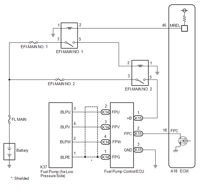
(for low pressure side) circuit consists of the ECM, fuel pump (for low
pressure side) and fuel pump control ECU (which operates the fuel pump
(for low pressure side)). Based on the engine output, the ECM determines
the fuel pump speed. The speed is then converted to a duty signal and
sent to the fuel pump control ECU. Based on the signal sent from the
ECM, the fuel pump control ECU adjusts the fuel pump (for low pressure
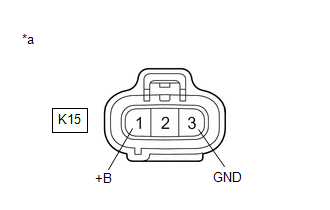
side) operation speed. WIRING DIAGRAM CAUTION / NOTICE / HINT NOTICE: Inspect the fuses for circuits related to this system before performing the following procedure. PROCEDURE 1. INSPECT FUEL PUMP CONTROL ECU *1 Fuel Pump Control ECU - - (a) Remove the fuel pump control ECU. Click here
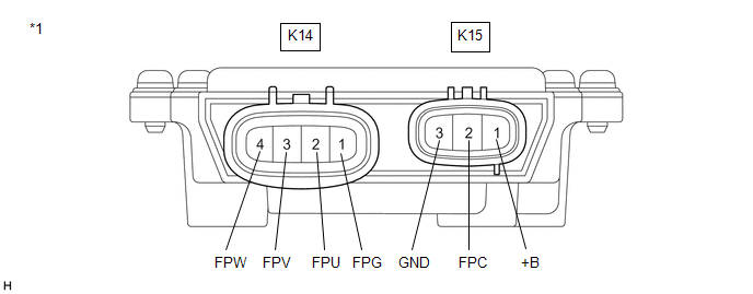
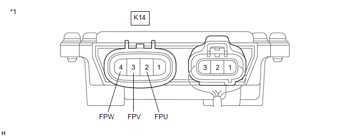
(b) Measure the resistance according to the value(s) in the table below. Standard Resistance: Tester Connection Condition Specified Condition K15-1 (+B) - K15-3 (GND) Always 200 Ω or higher K15-1 (+B) - K15-2 (FPC) Always 2 kΩ or higher K15-2 (FPC) - K15-3 (GND) Always 10 kΩ or higher K14-1 (FPG) - K15-3 (GND) Always 1 kΩ or higher K14-2 (FPU) - K15-3 (GND) Always 2 kΩ or higher K14-3 (FPV) - K15-3 (GND) Always 2 kΩ or higher K14-4 (FPW) - K15-3 (GND) Always 2 kΩ or higher HINT: This procedure checks for an internal short of the fuel pump control ECU when its transistor is stuck on. REPLACE FUEL PUMP CONTROL ECU 2. CHECK HARNESS AND CONNECTOR (POWER SOURCE OF FUEL PUMP CONTROL ECU) *a Front view of wire harness connector (to Fuel Pump Control ECU) (a) Disconnect the fuel pump control ECU connector. (b) Turn the engine switch on (IG). (c) Measure the voltage according to the value(s) in the table below. Standard Voltage: Tester Connection Condition Specified Condition K15-1 (+B) - K15-3 (GND) Engine switch on (IG) 11 to 14 V HINT: Make a note of the measured voltage as it may be used in a following Active Test. GO TO STEP 7 3. CHECK HARNESS AND CONNECTOR (FUEL PUMP CONTROL ECU - ECM) (a) Disconnect the fuel pump control ECU assembly connector. (b) Disconnect the ECM connector. (c) Measure the resistance according to the value(s) in the table below. Standard Resistance: Tester Connection Condition Specified Condition K15-2 (FPC) - A18-18 (FPC) Always Below 1 Ω K15-2 (FPC) or A18-18 (FPC) - Body ground and other terminals Always 10 kΩ or higher REPAIR OR REPLACE HARNESS OR CONNECTOR 4. PERFORM ACTIVE TEST USING TECHSTREAM (FUEL PUMP SINGLE PHASE ENERGIZATION) *1 Fuel Pump Control ECU - - (a) Disconnect the K14 fuel pump control ECU connector. (b) Connect the Techstream to the DLC3. (c) Turn the engine switch on (IG). (d) Turn the Techstream on. (e) Enter the following menus: Powertrain / Engine / Active Test / Fuel Pump Single Phase Energization. Tester Display Fuel Pump Single Phase Energization (f)
Operate the fuel pump control ECU using the Active Test function and
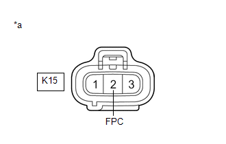
measure the voltage according to the value(s) in the table below. Standard Voltage: Tester Connection Techstream Operation Specified Condition K14-2 (FPU) - Body ground U Phase 4.4 to 8.4 V* K14-3 (FPV) - Body ground V Phase 4.4 to 8.4 V* K14-4 (FPW) - Body ground W Phase 4.4 to 8.4 V* HINT: Result Proceed to The U phase, V phase and W phase are all normal A The U phase, V phase or W phase is abnormal B The U phase, V phase and W phase are all abnormal C REPLACE FUEL PUMP CONTROL ECU GO TO STEP 6 5. CHECK HARNESS AND CONNECTOR (FUEL PUMP CONTROL ECU - FUEL PUMP (FOR LOW PRESSURE SIDE)) (a) Disconnect the fuel pump control ECU connector. (b) Disconnect the fuel pump (for low pressure side) connector. (c) Measure the resistance according to the value(s) in the table below. Standard Resistance: Tester Connection Condition Specified Condition K14-2 (FPU) - K37-3 (BLPU) Always Below 1 Ω K14-3 (FPV) - K37-4 (BLPV) Always Below 1 Ω K14-4 (FPW) - K37-2 (BLPW) Always Below 1 Ω K14-2 (FPU) or K37-3 (BLPU) - Body ground and other terminals Always 10 kΩ or higher K14-3 (FPV) or K37-4 (BLPV) - Body ground and other terminals Always 10 kΩ or higher K14-4 (FPW) or K37-2 (BLPW) - Body ground and other terminals Always 10 kΩ or higher HINT: Perform "Inspection After Repair" after replacing the fuel pump (for low pressure side). Click here REPLACE FUEL PUMP (FOR LOW PRESSURE SIDE) REPAIR OR REPLACE HARNESS OR CONNECTOR 6. INSPECT ECM (FPC TERMINAL) *a Front view of wire harness connector (to Fuel Pump Control ECU) (a) Disconnect the fuel pump control ECU connector. (b) Connect the Techstream to the DLC3. (c) Turn the engine switch on (IG). (d) Turn the Techstream on. (e) Enter the following menus: Powertrain / Engine / Active Test / Fuel Pump Single Phase Energization. Tester Display Fuel Pump Single Phase Energization (f)
Operate the fuel pump control ECU using the Active Test function and
measure the resistance according to the value(s) in the table below. Standard Resistance: Tester Connection Techstream Operation Specified Condition K15-2 (FPC) - Body ground Before Active Test → During Active Test Before Active Test: Resistance is stable → During Active Test: Resistance fluctuates* HINT: *:
Using the Active Test, duty control of the transistors in the ECM will
be performed. Due to the duty control, resistance of the FPC terminal
will be unstable during the Active Test. If the resistance is stable
before the Active Test and fluctuates while performing the Active Test,
it can be determined that the transistor is operating. If the transistor
does not operate during the Active Test, the ECM may be malfunctioning. REPLACE FUEL PUMP CONTROL ECU REPLACE ECM 7. CHECK HARNESS AND CONNECTOR (POWER SOURCE VOLTAGE OF EFI-MAIN NO. 2 RELAY) (a) Remove the EFI-MAIN NO. 2 relay from the No. 1 engine room relay block and No. 1 junction block assembly. (b) Measure the voltage according to the value(s) in the table below. Standard Voltage: Tester Connection Condition Specified Condition 3 (EFI-MAIN NO. 2 relay) - Body ground Always 11 to 14 V REPAIR OR REPLACE HARNESS OR CONNECTOR (BATTERY - EFI-MAIN NO. 2 RELAY) 8. INSPECT EFI-MAIN NO. 2 RELAY (a) Inspect the EFI-MAIN NO. 2 relay. Click here REPLACE EFI-MAIN NO. 2 RELAY 9. CHECK HARNESS AND CONNECTOR (EFI-MAIN NO. 1 RELAY - ECM) (a) Remove the EFI-MAIN NO. 1 relay from the No. 1 engine room relay block and No. 1 junction block assembly. (b) Disconnect the ECM connector. (c) Measure the resistance according to the value(s) in the table below. Standard Resistance: Tester Connection Condition Specified Condition 2 (EFI-MAIN NO. 1 relay) - A18-46 (MREL) Always Below 1 Ω 2 (EFI-MAIN NO. 1 relay) or A18-46 (MREL) - Body ground and other terminals Always 10 kΩ or higher REPAIR OR REPLACE HARNESS OR CONNECTOR 10. CHECK HARNESS AND CONNECTOR (EFI-MAIN NO. 1 RELAY - EFI-MAIN NO. 2 RELAY) (a)
Remove the EFI-MAIN NO. 1 and EFI-MAIN NO. 2 relays from the No. 1
engine room relay block and No. 1 junction block assembly. (b) Measure the resistance according to the value(s) in the table below. Standard Resistance: Tester Connection Condition Specified Condition 5 (EFI-MAIN NO. 1 relay) - 2 (EFI-MAIN NO. 2 relay) Always Below 1 Ω 5 (EFI-MAIN NO. 1 relay) or 2 (EFI-MAIN NO. 2 relay) - Body ground and other terminals Always 10 kΩ or higher REPAIR OR REPLACE HARNESS OR CONNECTOR 11. CHECK HARNESS AND CONNECTOR (EFI-MAIN NO. 2 RELAY - BODY GROUND) (a) Remove the EFI-MAIN NO. 2 relay from the No. 1 engine room relay block and No. 1 junction block assembly. (b) Measure the resistance according to the value(s) in the table below. Standard Resistance: Tester Connection Condition Specified Condition 1 (EFI-MAIN NO. 2 relay) - Body ground Always Below 1 Ω REPAIR OR REPLACE HARNESS OR CONNECTOR 12. CHECK HARNESS AND CONNECTOR (EFI-MAIN NO. 2 RELAY - FUEL PUMP CONTROL ECU) (a) Remove the EFI-MAIN NO. 2 relay from the No. 1 engine room relay block and No. 1 junction block assembly. (b) Disconnect the fuel pump control ECU connector. (c) Measure the resistance according to the value(s) in the table below. Standard Resistance: Tester Connection Condition Specified Condition 5 (EFI-MAIN NO. 2 relay) - K15-1 (+B) Always Below 1 Ω 5 (EFI-MAIN NO. 2 relay) or K15-1 (+B) - Body ground and other terminals Always 10 kΩ or higher REPAIR OR REPLACE HARNESS OR CONNECTOR 13. CHECK HARNESS AND CONNECTOR (FUEL PUMP CONTROL ECU - BODY GROUND) (a) Disconnect the fuel pump control ECU connector. (b) Measure the resistance according to the value(s) in the table below. Standard Resistance: Tester Connection Condition Specified Condition K15-3 (GND) - Body ground Always Below 1 Ω GO TO ECM POWER SOURCE CIRCUIT REPAIR OR REPLACE HARNESS OR CONNECTORFail-safe Chart
Freeze Frame Data
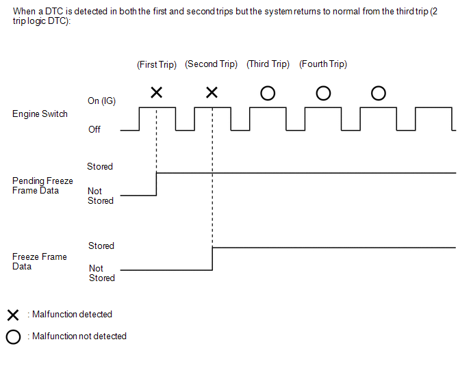
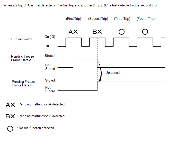
Fuel Pump Control Circuit

NG

OK

NG

OK

NG

OK

B

C

A


OK

NG

OK

NG

NG

OK


NG

OK

NG

OK

NG

OK

NG

OK

NG

OK

OK

NG

Toyota Avalon (XX50) 2019-2022 Service & Repair Manual > Seat: Front Power Seat Control System(for Gasoline Model With Memory)
Slide Sensor Malfunction (B2650) DESCRIPTION When the position control ECU assembly does not receive a slide motor position sensor signal despite the seat having been moved forward or backward by power seat motor operation, this DTC is stored. DTC No. Detection Item DTC Detection Condition Trouble A ...