Components
COMPONENTS
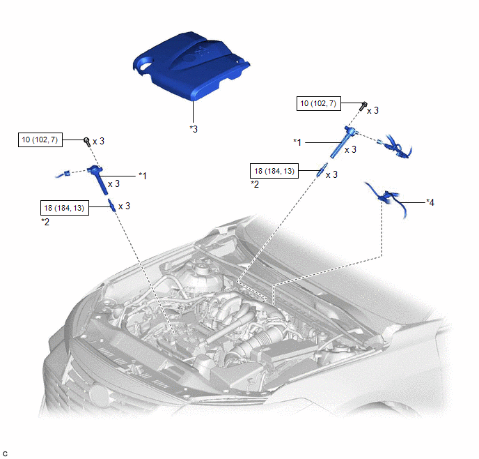
ILLUSTRATION
|
*1 | IGNITION COIL ASSEMBLY |
*2 | SPARK PLUG |
|
*3 | V-BANK COVER SUB-ASSEMBLY |
*4 | VACUUM HOSE |
 |
N*m (kgf*cm, ft.*lbf): Specified torque |
- | - |
Installation
INSTALLATION
PROCEDURE
1. INSTALL SPARK PLUG
Click here 
2. INSTALL IGNITION COIL ASSEMBLY
HINT:
Perform "Inspection After Repair" after replacing an ignition coil assembly.
Click here
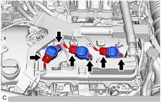
(a) Install the 3 ignition coil assemblies to the cylinder head cover sub-assembly with the 3 bolts.
Torque:
10 N·m {102 kgf·cm, 7 ft·lbf}
NOTICE:
If an ignition coil assembly has been struck or dropped, replace it.
HINT:
Install the same parts to their original positions.
(b) Connect the 3 ignition coil assembly connectors.
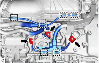
(c) Engage the 2 wire harness clamps.
(d) Engage the 4 clamps to install the vacuum hose to the intake air surge tank assembly.
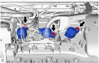
(e) Install the 3 ignition coil assemblies to the cylinder head cover sub-assembly LH with the 3 bolts.
Torque:
10 N·m {102 kgf·cm, 7 ft·lbf}
NOTICE:
If an ignition coil assembly has been struck or dropped, replace it.
HINT:
Install the same parts to their original positions.
(f) Connect the 3 ignition coil assembly connectors.
3. INSTALL V-BANK COVER SUB-ASSEMBLY
Click here
4. PERFORM INITIALIZATION
(a) Perform "Inspection After Repair" after replacing an ignition coil assembly or spark plug.
Click here
Removal
REMOVAL
CAUTION / NOTICE / HINT
The necessary procedures (adjustment, calibration, initialization, or registration) that must be performed after parts are removed and installed, or replaced during ignition coil assembly or spark plug removal/installation are shown below.
Necessary Procedures After Parts Removed/Installed/Replaced|
Replaced Part or Performed Procedure |
Necessary Procedure | Effect/Inoperative Function when Necessary Procedure not Performed |
Link |
|---|---|---|---|
| Inspection after repair |
|
|
PROCEDURE
1. REMOVE V-BANK COVER SUB-ASSEMBLY
Click here

2. REMOVE IGNITION COIL ASSEMBLY
| (a) Disconnect the 3 ignition coil assembly connectors. |
|
(b) Remove the 3 bolts and 3 ignition coil assemblies from the cylinder head cover sub-assembly LH.
NOTICE:
If an ignition coil assembly has been struck or dropped, replace it.
HINT:
Arrange the removed parts in the correct order.
| (c) Disengage the 4 clamps to separate the vacuum hose from the intake air surge tank assembly. |
|
(d) Disengage the 2 wire harness clamps.
(e) Disconnect the 3 ignition coil assembly connectors.
| (f) Remove the 3 bolts and 3 ignition coil assemblies from the cylinder head cover sub-assembly. NOTICE: If an ignition coil assembly has been struck or dropped, replace it. HINT: Arrange the removed parts in the correct order. |
|
3. REMOVE SPARK PLUG
Click here
Toyota Avalon (XX50) 2019-2022 Service & Repair Manual > Brake System (other): Brake Pedal(for Hv Model)
Adjustment ADJUSTMENT PROCEDURE 1. INSPECT AND ADJUST BRAKE PEDAL HEIGHT (a) Remove the front door scuff plate LH. Click here (b) Remove the cowl side trim sub-assembly LH. Click here (c) Remove the No. 1 instrument panel under cover sub-assembly. Click here (d) Remove the accelerator pedal pad. Cli ...