Components
COMPONENTS
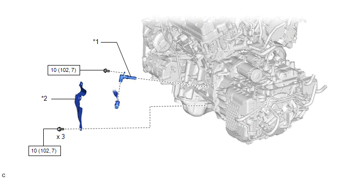
ILLUSTRATION
|
*1 | CRANKSHAFT POSITION SENSOR |
*2 | CRANKSHAFT POSITION SENSOR PROTECTOR |
 |
N*m (kgf*cm, ft.*lbf): Specified torque |
- | - |
Installation
INSTALLATION
PROCEDURE
1. INSTALL CRANKSHAFT POSITION SENSOR
(a) Apply a light coat of engine oil to the O-ring of the crankshaft position sensor.
NOTICE:
If reusing the crankshaft position sensor, be sure to inspect the O-ring.
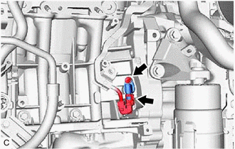
(b) Install the crankshaft position sensor to the cylinder block sub-assembly with the bolt.
Torque:
10 N·m {102 kgf·cm, 7 ft·lbf}
NOTICE:
(c) Connect the crankshaft position sensor connector.
2. INSTALL CRANKSHAFT POSITION SENSOR PROTECTOR
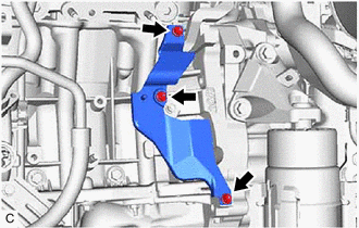
(a) Install the crankshaft position sensor protector to the cylinder block sub-assembly and oil pan sub-assembly with the 3 bolts.
Torque:
10 N·m {102 kgf·cm, 7 ft·lbf}
3. INSTALL EXHAUST MANIFOLD SUB-ASSEMBLY LH (TWC: Front Catalyst)
Click here

Removal
REMOVAL
CAUTION / NOTICE / HINT
The necessary procedures (adjustment, calibration, initialization or registration) that must be performed after parts are removed and installed, or replaced during crankshaft position sensor removal/installation are shown below.
Necessary Procedures After Parts Removed/Installed/Replaced|
Replaced Part or Performed Procedure |
Necessary Procedure | Effect/Inoperative Function when Necessary Procedure not Performed |
Link |
|---|---|---|---|
| Gas leak from exhaust system is repaired |
Inspection after repair |
|
|
PROCEDURE
1. REMOVE EXHAUST MANIFOLD SUB-ASSEMBLY LH (TWC: Front Catalyst)
Click here

2. REMOVE CRANKSHAFT POSITION SENSOR PROTECTOR
| (a) Remove the 3 bolts and crankshaft position sensor protector from the cylinder block sub-assembly and oil pan sub-assembly. |
|
3. REMOVE CRANKSHAFT POSITION SENSOR
| (a) Disconnect the crankshaft position sensor connector. |
|
(b) Remove the bolt and crankshaft position sensor from the cylinder block sub-assembly.
NOTICE:
If the crankshaft position sensor has been struck or dropped, replace it.
Toyota Avalon (XX50) 2019-2022 Service & Repair Manual > Smart Key System(for Start Function, Hv Model): Engine Immobiliser System Circuit Short to Battery (B279A12). Engine Immobiliser System Incorrect Assembly (B279C95). Ignition Hold Monitor Malfunction (B2271)
Engine Immobiliser System Circuit Short to Battery (B279A12) DESCRIPTION If the communication line (IMI - EFIO) between the hybrid vehicle control ECU and certification ECU (smart key ECU assembly) is stuck high, the hybrid vehicle control ECU will store this DTC. DTC No. Detection Item DTC Detectio ...