COMPONENTS ILLUSTRATION *1 CAMSHAFT TIMING GEAR BOLT *2 O-RING *3 CAMSHAFT TIMING OIL CONTROL SOLENOID ASSEMBLY (for Intake Side of Bank 2) - - N*m (kgf*cm, ft.*lbf): Specified torque ŌŚÅ Non-reusable part Adhesive 1324 Ōśģ Precoated part INSPECTION PROCEDURE 1. INSPECT CAMSHAFT TIMING GEAR BOLT (a) Check the stroke of the plunger in the center of the camshaft timing gear bolt. Standard Stroke: 4.5 mm (0.177 in.) or more HINT: When pressing the plunger, there may be a stepped feeling. This is not a malfunction. If the result is not as specified, replace the camshaft timing gear bolt. *a Plunger INSTALLATION PROCEDURE 1. INSTALL CAMSHAFT TIMING GEAR BOLT (a) Make sure that the No. 1 cylinder is at TDC/compression. HINT: Check
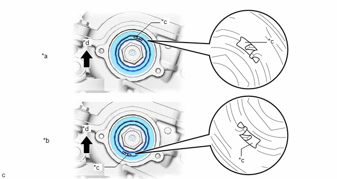
that the cutout of the camshaft timing gear assembly is at the top and
align the timing mark (cutout) of the crankshaft pulley with the timing
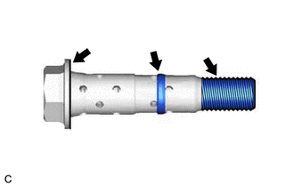
mark on the timing chain cover assembly. (b) Apply engine oil to the areas of the camshaft timing gear bolt shown in the illustration. (c) While holding the crankshaft pulley, temporarily install the camshaft timing gear bolt. Torque: 10 N┬Ęm {102 kgf┬Ęcm, 7 ft┬Ęlbf} NOTICE: HINT: Make
sure that the flange part of the camshaft timing gear bolt contacts the
entire circumference of the camshaft timing gear assembly. (d) While holding the crankshaft pulley, loosen the camshaft timing gear bolt 60 to 180┬░. (e) Turn the crankshaft pulley clockwise 30 to 90┬░. (f) While holding the crankshaft pulley, tighten the camshaft timing gear bolt. Torque: 95 N┬Ęm {969 kgf┬Ęcm, 70 ft┬Ęlbf} NOTICE: Do not use an impact wrench. 2. INSTALL CAMSHAFT TIMING OIL CONTROL SOLENOID ASSEMBLY (for Intake Side of Bank 2) Click here 3. INSTALL ENGINE ASSEMBLY WITH TRANSAXLE Click here REMOVAL CAUTION / NOTICE / HINT The
necessary procedures (adjustment, calibration, initialization, or
registration) that must be performed after parts are removed and
installed, or replaced during camshaft timing gear bolt
removal/installation are shown below. Replaced Part or Performed Procedure Necessary Procedure Effect/Inoperative Function when Necessary Procedure not Performed Link Battery terminal is disconnected/reconnected Perform steering sensor zero point calibration Lane departure alert system (w/ Steering Control) Pre-collision system Intelligent Clearance Sonar System*1 Lighting System (for Gasoline Model with Cornering Light) Memorize steering angle neutral point Parking Assist Monitor System Panoramic View Monitor System Replacement of ECM Vehicle Identification Number (VIN) registration MIL comes on
ECU communication ID registration (Immobiliser system) Engine start function Gas leak from exhaust system is repaired Inspection after repair
Replacement of ECM (If transaxle compensation code read from ECM)
Replacement of ECM (If transaxle compensation code not read from ECM) Replacement of ECM Code registration (Smart Key System (for Start Function))
Suspension, tires, etc.
Rear television camera assembly optical axis adjustment (Back camera position setting) Parking Assist Monitor System
Panoramic View Monitor System
Perform headlight ECU sub-assembly LH initialization Lighting system (for Gasoline Model with Cornering Light) Front wheel alignment adjustment Perform system variant learning and acceleration sensor zero point calibration.
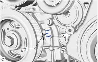
Click here PROCEDURE 1. REMOVE ENGINE ASSEMBLY WITH TRANSAXLE Click here 2. REMOVE CAMSHAFT TIMING OIL CONTROL SOLENOID ASSEMBLY (for Intake Side of Bank 2) Click here 3. SET NO. 1 CYLINDER TO TDC/COMPRESSION (a)
Turn the crankshaft pulley clockwise until its timing mark (cutout) is
aligned with the timing mark on the timing chain cover assembly as shown
in the illustration. *a Timing Mark *b Timing Mark (Cutout) (b) Check that the cutout of the camshaft timing gear assembly is at the top. *a Correct *b Incorrect *c Cutout *d Up HINT: If
the cutout of the camshaft timing gear assembly is not at the top, turn
the crankshaft 360┬░ clockwise and align the timing mark (cutout) of the
crankshaft pulley with the timing mark on the timing chain cover
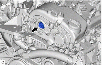
assembly again. 4. REMOVE CAMSHAFT TIMING GEAR BOLT (a) While holding the crankshaft pulley, remove the camshaft timing gear bolt. NOTICE: Components
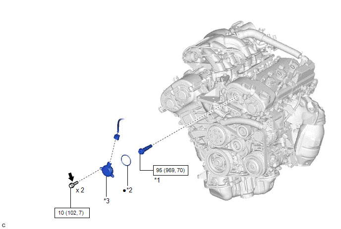


Inspection
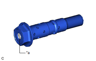
Installation


Removal


 for Initialization
 for Registration


 for Initialization
 for Calibration
 for Initialization
 for Calibration


Toyota Avalon (XX50) 2019-2022 Service & Repair Manual > Sfi System: Fuel Rail Pressure Sensor "A" Circuit Short to Ground (P019011). Fuel Rail Pressure Sensor "A" Circuit Short to Battery or Open (P019015). Engine Oil Temperature Sensor Circuit Short to Ground (P01951
Fuel Rail Pressure Sensor "A" Circuit Short to Ground (P019011) DESCRIPTION The fuel pressure sensor (for high pressure side) is installed on the fuel delivery pipe (for high pressure side). The fuel pressure sensor (for high pressure side) changes the fuel pressure for high pressure side into an el ...