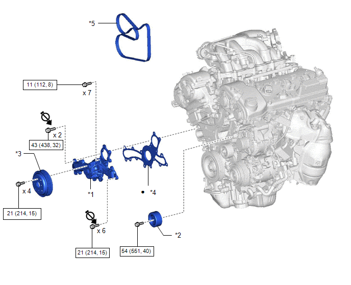
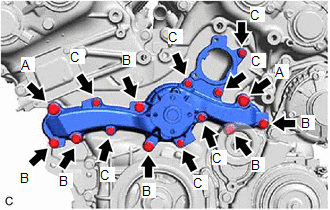
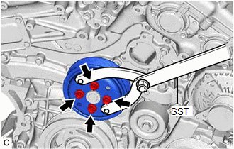
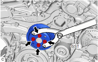
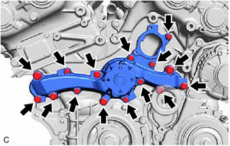
COMPONENTS ILLUSTRATION *1 ENGINE WATER PUMP ASSEMBLY *2 NO. 2 IDLER PULLEY SUB-ASSEMBLY *3 WATER PUMP PULLEY *4 WATER PUMP GASKET *5 V-RIBBED BELT - - N*m (kgf*cm, ft.*lbf): Specified torque ● Non-reusable part Do not apply lubricants to the threaded parts - - INSTALLATION PROCEDURE 1. INSTALL ENGINE WATER PUMP ASSEMBLY (a) Install a new water pump gasket and the engine water pump assembly with the 15 bolts. Torque: Bolt (A) : 43 N·m {438 kgf·cm, 32 ft·lbf} Bolt (B) : 21 N·m {214 kgf·cm, 15 ft·lbf} Bolt (C) : 11 N·m {112 kgf·cm, 8 ft·lbf} Standard Length: Item Length Bolt (A) 60 mm (2.36 in.) Bolt (B) 55 mm (2.17 in.) Bolt (C) 22 mm (0.866 in.) NOTICE: 2. INSTALL WATER PUMP PULLEY (a) Temporarily install the water pump pulley with the 4 bolts. (b) Using SST, hold the water pump pulley. SST: 09960-10010 09962-01000 09963-00700 (c) Fully tighten the 4 bolts. Torque: 21 N·m {214 kgf·cm, 15 ft·lbf} 3. INSTALL NO. 2 IDLER PULLEY SUB-ASSEMBLY (a) Install the No. 2 idler pulley sub-assembly with the bolt. Torque: 54 N·m {551 kgf·cm, 40 ft·lbf} 4. INSTALL V-RIBBED BELT Click here 5. INSTALL WATER INLET WITH THERMOSTAT SUB-ASSEMBLY Click here ON-VEHICLE INSPECTION PROCEDURE 1. INSPECT FOR COOLANT LEAK HINT: (a) Visually check the engine water pump assembly. (1) Check that engine coolant is not dripping from the engine water pump assembly. HINT: (b) Remove the V-ribbed belt. Click here
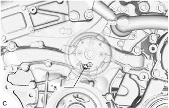
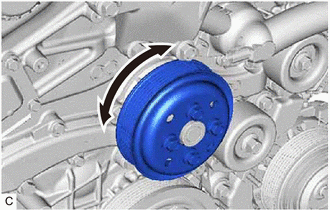
(c) Remove the water pump pulley. Click here HINT: Move the water pump pulley so that the drain plug can be reached. (d) Inspect the area around the engine water pump assembly. HINT: Check for deposits around the drain plug of the engine water pump assembly. (1)
Press a piece of paper towel against the drain plug and check that the
paper towel is not wet and that there are no deposits on the lip of the
drain plug. If the paper towel is wet, replace the engine water pump assembly. If the paper towel is not wet, thoroughly clean the area around the engine water pump assembly. *a Drain Plug (e) Install the water pump pulley. Click here
2. INSPECT ENGINE WATER PUMP ASSEMBLY (a) Turn the water pump pulley and check that the bearing of the engine water pump assembly moves smoothly and quietly. If necessary, replace the engine water pump assembly. (b) Install the V-ribbed belt. Click here
REMOVAL CAUTION / NOTICE / HINT The
necessary procedures (adjustment, calibration, initialization or
registration) that must be performed after parts are removed and
installed, or replaced during engine water pump assembly
removal/installation are shown below. Replaced Part or Performed Procedure Necessary Procedure Effect/Inoperative Function when Necessary Procedure not Performed Link Battery terminal is disconnected/reconnected Perform steering sensor zero point calibration Lane departure alert system (w/ Steering Control) Pre-collision system Intelligent Clearance Sonar System*1 Lighting System (for Gasoline Model with Cornering Light) Memorize steering angle neutral point Parking Assist Monitor System Panoramic View Monitor System Replacement of ECM Vehicle Identification Number (VIN) registration MIL comes on
ECU communication ID registration (Immobiliser system) Engine start function Inspection after repair
Replacement of automatic transaxle assembly
Replacement of ECM (If transaxle compensation code read from ECM) Replacement of ECM (If transaxle compensation code not read from ECM) Replacement of automatic transaxle fluid ATF thermal degradation estimate reset The value of the Data List item "ATF Thermal Degradation Estimate" is not estimated correctly Replacement of ECM Code registration (Smart Key System (for Start Function))
Suspension, tires, etc.
Rear television camera assembly optical axis adjustment (Back camera position setting) Parking Assist Monitor System
Panoramic View Monitor System
Perform headlight ECU sub-assembly LH initialization Lighting system (for Gasoline Model with Cornering Light) Front wheel alignment adjustment Perform system variant learning and acceleration sensor zero point calibration.
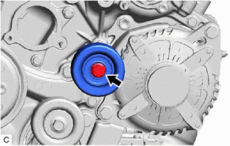
Click here PROCEDURE 1. REMOVE WATER INLET WITH THERMOSTAT SUB-ASSEMBLY Click here 2. REMOVE V-RIBBED BELT Click here 3. REMOVE NO. 2 IDLER PULLEY SUB-ASSEMBLY (a) Remove the bolt and No. 2 idler pulley sub-assembly. 4. REMOVE WATER PUMP PULLEY (a) Using SST, hold the water pump pulley. SST: 09960-10010 09962-01000 09963-00700 (b) Remove the 4 bolts and water pump pulley. 5. REMOVE ENGINE WATER PUMP ASSEMBLY (a) Remove the 15 bolts, engine water pump assembly and water pump gasket.Components


Installation


On-vehicle Inspection




Removal


 for Initialization
 for Registration


 for Initialization
 for Calibration
 for Initialization
 for Calibration


Toyota Avalon (XX50) 2019-2022 Service & Repair Manual > 2gr-fks Battery / Charging: Generator
Components COMPONENTS ILLUSTRATION *1 GENERATOR ASSEMBLY *2 WIRE HARNESS CLAMP BRACKET *3 GENERATOR ASSEMBLY BRACKET *4 V-BANK COVER SUB-ASSEMBLY Tightening torque for "Major areas involving basic vehicle performance such as moving/turning/stopping": N*m (kgf*cm, ft.*lbf) N*m (kgf*cm, ft.*lbf): Spec ...