Components
COMPONENTS
ILLUSTRATION
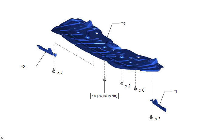
|
*1 | FRONT WHEEL OPENING EXTENSION PAD LH |
*2 | FRONT WHEEL OPENING EXTENSION PAD RH |
|
*3 | NO. 1 ENGINE UNDER COVER |
- | - |
 |
N*m (kgf*cm, ft.*lbf): Specified torque |
- | - |
ILLUSTRATION
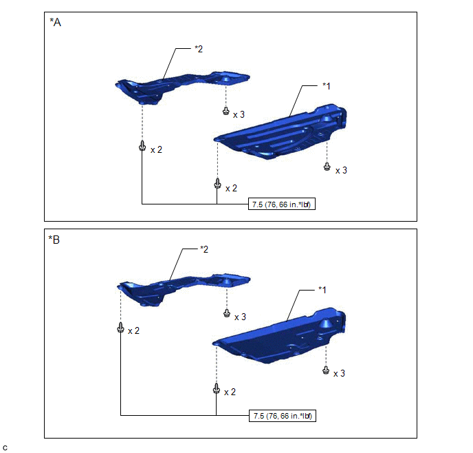
|
*A | Type A |
*B | Type B |
|
*1 | REAR ENGINE UNDER COVER LH |
*2 | REAR ENGINE UNDER COVER RH |
 |
N*m (kgf*cm, ft.*lbf): Specified torque |
- | - |
ILLUSTRATION
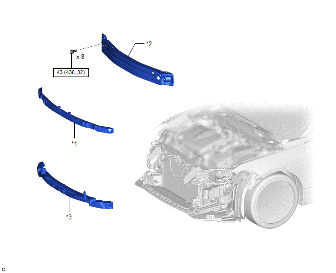
|
*1 | FRONT BUMPER ENERGY ABSORBER |
*2 | FRONT BUMPER REINFORCEMENT |
|
*3 | NO. 2 FRONT BUMPER ENERGY ABSORBER |
- | - |
 |
N*m (kgf*cm, ft.*lbf): Specified torque |
- | - |
ILLUSTRATION
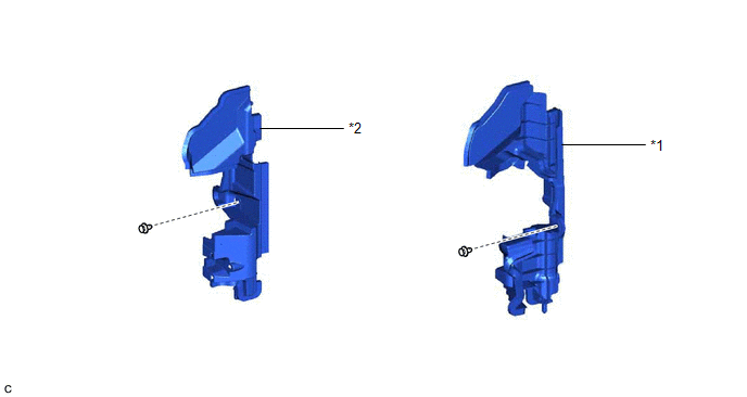
|
*1 | NO. 1 RADIATOR AIR GUIDE LH |
*2 | NO. 1 RADIATOR AIR GUIDE RH |
ILLUSTRATION
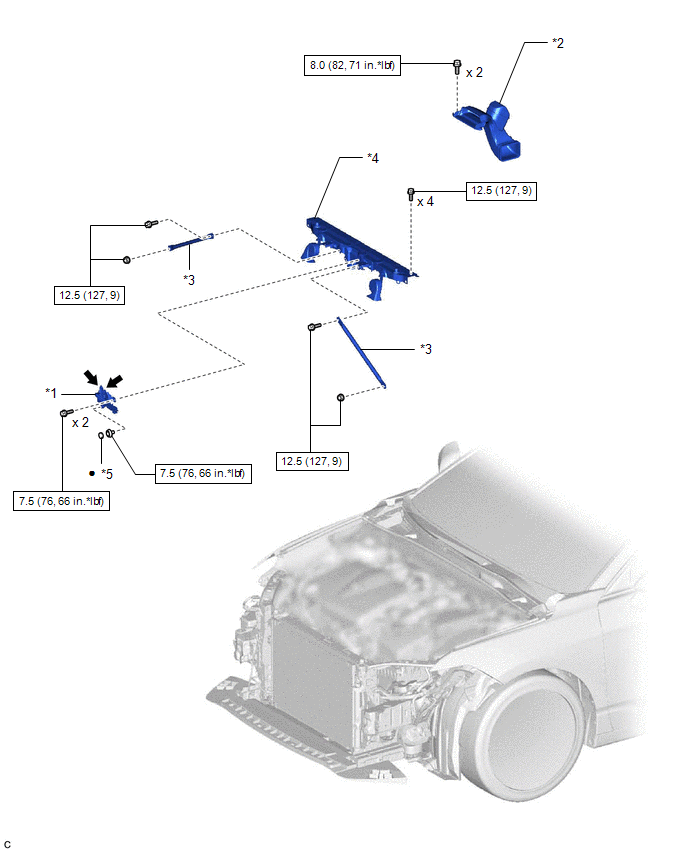
|
*1 | HOOD LOCK ASSEMBLY |
*2 | INLET AIR CLEANER ASSEMBLY |
|
*3 | UPPER RADIATOR MOUNTING BRACKET |
*4 | UPPER RADIATOR SUPPORT SUB-ASSEMBLY |
|
*5 | HOOD LOCK NUT CAP |
- | - |
 |
N*m (kgf*cm, ft.*lbf): Specified torque |
â—Ź | Non-reusable part |
 |
MP grease | - |
- |
ILLUSTRATION
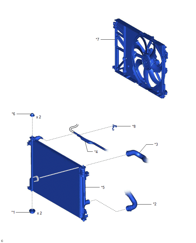
|
*1 | LOWER RADIATOR SUPPORT |
*2 | NO. 1 RADIATOR HOSE |
|
*3 | NO. 2 RADIATOR HOSE |
*4 | NO. 5 WATER BY-PASS HOSE |
|
*5 | RADIATOR ASSEMBLY |
*6 | RADIATOR SUPPORT CUSHION |
|
*7 | FAN WITH MOTOR ASSEMBLY |
*8 | HOSE CLAMP |
Installation
INSTALLATION
PROCEDURE
1. INSTALL LOWER RADIATOR SUPPORT
(a) Install the 2 lower radiator supports to the radiator assembly.
2. INSTALL RADIATOR SUPPORT CUSHION
(a) Install the 2 radiator support cushions to the radiator assembly.
3. INSTALL RADIATOR ASSEMBLY
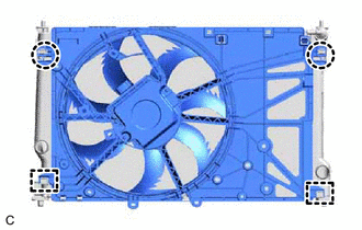
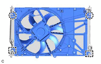
(a) Engage the 2 guides.
(b) Engage the 2 claws to install the fan with motor assembly to the radiator assembly.
NOTICE:
Do not damage the radiator assembly when installing the fan with motor assembly.
(c) Install the radiator assembly with the fan with motor assembly to the vehicle body.
NOTICE:
Do
not apply excessive force to the cooler condenser assembly or pipe when
installing the radiator assembly with the fan with motor assembly.
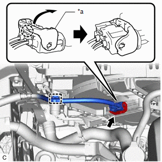
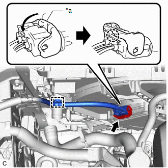
(d) Connect the cooling fan motor connector.
| (1) Engage the wire harness clamp. | |
(2) Connect the cooling fan motor connector and push down the lock lever to engage the claw as shown in the illustration.
NOTICE:
- When connecting the cooling fan motor connector, make sure that the
connecting parts of the cooling fan motor connector are free of dirt,
water or other foreign matter.
- Be sure to securely connect the cooling fan motor connector.
(e) Engage the 2 guides.
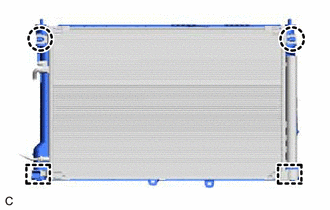
(f) Engage the 2 claws to install the cooler condenser assembly to the radiator assembly.
NOTICE:
Make sure not to damage the cooler condenser assembly when installing the cooler condenser assembly.
4. CONNECT NO. 2 RADIATOR HOSE
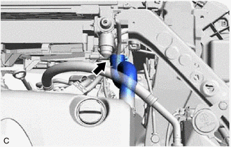
(a) Connect the No. 2 radiator hose to the radiator assembly and slide the clip to secure it.
5. CONNECT NO. 1 RADIATOR HOSE
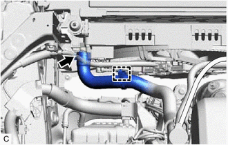
(a) Connect the No. 1 radiator hose to the radiator assembly and slide the clip to secure it.
(b) Engage the clamp to connect the No. 1 radiator hose to the fan with motor assembly.
6. CONNECT NO. 5 WATER BY-PASS HOSE
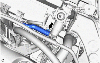
(a) Connect the No. 5 water by-pass hose to the radiator assembly and slide the clip to secure it.
(b) Engage the 2 clamps to install the hose clamp (B) to the No. 5 water by-pass hose and No. 6 water by-pass hose.
(c) Engage the 4 clamps to connect the No. 5 water by-pass hose and No. 6 water by-pass hose to the hose clamp (A).
7. INSTALL UPPER RADIATOR SUPPORT SUB-ASSEMBLY
(a) Install the upper radiator support sub-assembly with the 4 bolts.
Torque:
12.5 N·m {127 kgf·cm, 9 ft·lbf}
(b) Engage the clamp to connect the hood lock control cable assembly to the upper radiator support sub-assembly.
8. INSTALL NO. 1 RADIATOR AIR GUIDE RH
(a) Engage the guide and claw.
(b) Install the No. 1 radiator air guide RH with the clip.
9. INSTALL NO. 1 RADIATOR AIR GUIDE LH
(a) Engage the guide and claw.
(b) Install the No. 1 radiator air guide LH with the front radiator side air guide plate LH with the clip.
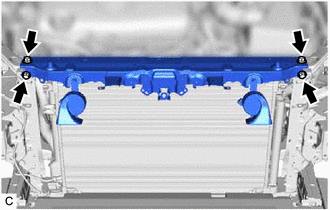
10. INSTALL UPPER RADIATOR MOUNTING BRACKET
(a) Install the 2 upper radiator mounting brackets with the 2 bolts and 2 nuts.
Torque:
12.5 N·m {127 kgf·cm, 9 ft·lbf}
(b) Connect the 2 horn connectors.
11. INSTALL INLET AIR CLEANER ASSEMBLY
Click here

12. INSTALL HOOD LOCK ASSEMBLY
Click here

13. INSTALL FRONT BUMPER REINFORCEMENT
Click here 
14. INSTALL FRONT BUMPER ENERGY ABSORBER
Click here 
15. INSTALL NO. 2 FRONT BUMPER ENERGY ABSORBER
Click here 
16. INSTALL THERMISTOR ASSEMBLY
Click here 
17. INSTALL HEADLIGHT ASSEMBLY
Click here 
18. ADD ENGINE COOLANT
Click here 
19. INSPECT FOR COOLANT LEAK
Click here 
20. INSTALL REAR ENGINE UNDER COVER RH
Click here 
21. INSTALL REAR ENGINE UNDER COVER LH
Click here 
22. INSTALL NO. 1 ENGINE UNDER COVER
Click here 
23. INSTALL FRONT WHEEL OPENING EXTENSION PAD RH
Click here 
24. INSTALL FRONT WHEEL OPENING EXTENSION PAD LH
Click here 
On-vehicle Inspection
ON-VEHICLE INSPECTION
CAUTION / NOTICE / HINT
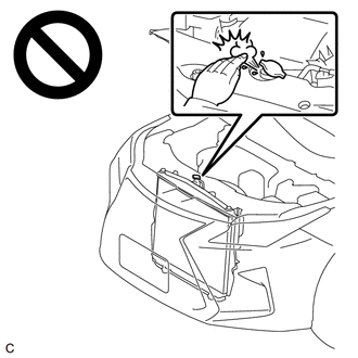
CAUTION:
Do
not remove the radiator cap sub-assembly while the engine and radiator
assembly are still hot. Pressurized, hot engine coolant and steam may be
released and cause serious burns.
PROCEDURE
1. CHECK RADIATOR CAP SUB-ASSEMBLY
CAUTION:
Do
not remove the radiator cap sub-assembly while the engine and radiator
assembly are still hot. Pressurized, hot engine coolant and steam may be
released and cause serious burns.
(a) Measure the valve opening pressure.
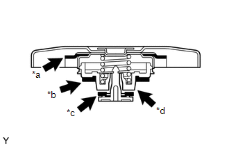
|
*a | Rubber Packing (1) |
|
*b | Rubber Packing (2) |
|
*c | Rubber Packing (3) |
|
*d | Valve Seat |
(1)
If there are water stains or foreign matter on the rubber packing (1),
(2) or (3), clean the part(s) with water and finger scouring.
(2) Check that the rubber packings (1), (2) and (3) are not deformed, cracked or swollen.
(3) Check that the rubber packing (3) and valve seat are not stuck together.
(4) Apply engine coolant to the rubber packings (2) and (3) before using a radiator cap tester.
| (5) When using the radiator cap tester, tilt it upward 30° or more. |
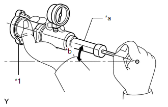 |
|
*1 | Radiator Cap Sub-assembly | |
*a | Radiator Cap Tester | |
*b | 30° or more | | |
(6) Pump the radiator cap tester several times, and check the maximum pressure.
Pumping Speed:
1 pump per second
|
Item | Specified Condition |
|
Standard pressure (for brand-new radiator cap sub-assembly) |
94 to 122 kPa (1.0 to 1.2 kgf/cm2, 13.6 to 17.6 psi) |
|
Minimum pressure (for used radiator cap sub-assembly) |
79 kPa (0.8 kgf/cm2, 11.5 psi) |
HINT:
Even if the radiator cap sub-assembly cannot maintain the maximum pressure, it is not a defect.
If the maximum pressure is less than the minimum pressure, replace the radiator cap sub-assembly.
2. CHECK RADIATOR ASSEMBLY FOR CLOGGING
CAUTION:
To prevent burns, do not touch the engine or other high temperature components while the engine is hot.
(a) Remove the cool air intake duct seal.
Click here

(b) Remove the inlet air cleaner assembly.
Click here 
(c)
Shine an electric light at the radiator assembly and cooler condenser
assembly from the front of the cooler condenser assembly and check the
radiator assembly for clogging using a mirror.
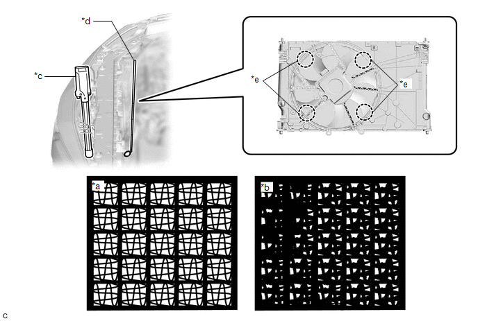
|
*a | OK |
*b | NG |
|
*c | Electric Light |
*d | Mirror |
|
*e | Areas to be checked |
- | - |
OK:
The radiator assembly is not clogged.
If the radiator assembly is clogged, clean it.
(d) Install the inlet air cleaner assembly.
Click here

(e) Install the cool air intake duct seal.
Click here 
3. CLEAN RADIATOR ASSEMBLY
CAUTION:
To prevent burns, do not touch the engine or other high temperature components while the engine is hot.
(a) Remove the cool air intake duct seal.
Click here

(b) Remove the inlet air cleaner assembly.
Click here 
(c) Cover the opening of each air duct with a piece of cloth.
(d) Clean the cooler condenser assembly.
(1) Check that the washer nozzle is not clogged.
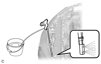
| (2) Insert the washer nozzle into the space in front of the cooler condenser assembly and spray it.
NOTICE:
- Clean the fins of the cooler condenser assembly by spraying the entire area for 150 seconds. Repeat this process twice.
- Set the air pressure to 0.4 MPa (4.1 kgf/cm2, 58 psi).
- Check that water sprays in mist form from the nozzle.
- Keep the nozzle parallel to the cooler condenser assembly.
- Do not allow the nozzle to contact the fins of the cooler condenser assembly.
- Keep the nozzle moving while spraying water.
- Do not spray the cooler compressor assembly or generator assembly excessively.
| |
(3) Leave the cooler condenser assembly as is for 10 minutes to let the water penetrate the dirt.
(4) Clean the cooler condenser assembly again.
NOTICE:
- Clean the fins of the cooler condenser assembly by spraying the entire area for 150 seconds. Repeat this process 4 times.
- Set the air pressure to 0.4 MPa (4.1 kgf/cm2, 58 psi).
- Check that water sprays in mist form from the nozzle.
- Keep the nozzle parallel to the cooler condenser assembly.
- Do not allow the nozzle to contact the fins of the cooler condenser assembly.
- Keep the nozzle moving while spraying water.
- Do not spray the cooler compressor assembly or generator assembly excessively.
(5) Using an air blow gun, dry the cooler condenser assembly for 3 minutes.
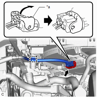
(e) Disconnect the cooling fan motor connector.
| (1) Disengage the claw and raise the lock lever to disconnect the cooling fan motor connector as shown in the illustration.
NOTICE: After
disconnecting the cooling fan motor connector, make sure that dirt,
water or other foreign matter does not contact the connecting parts of
the cooling fan motor connector. | |
(2) Disengage the wire harness clamp.
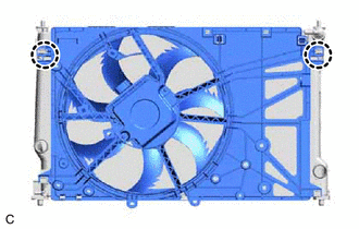
| (f) Disengage the 2 claws and separate the fan with motor assembly from the radiator assembly. |
|
(g) Clean the radiator assembly.
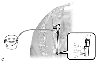
| (1) Insert the washer nozzle between the radiator assembly and fan with motor assembly and spray the radiator assembly.
NOTICE:
- Clean the fins of the radiator assembly by spraying the entire area for 150 seconds. Repeat this process twice.
- Set the air pressure to 0.4 MPa (4.1 kgf/cm2, 58 psi).
- Check that water sprays in mist form from the nozzle.
- Keep the nozzle parallel to the radiator assembly.
- Do not allow the nozzle to contact the fins of the radiator assembly.
- Keep the nozzle moving while spraying water.
| |
(2) Leave the radiator assembly as is for 10 minutes to let the water penetrate the dirt.
(3) Clean the radiator assembly again.
NOTICE:
- Clean the fins of the radiator assembly by spraying the entire area for 150 seconds. Repeat this process 4 times.
- Set the air pressure to 0.4 MPa (4.1 kgf/cm2, 58 psi).
- Check that water sprays in mist form from the nozzle.
- Keep the nozzle parallel to the radiator assembly.
- Do not allow the nozzle to contact the fins of the radiator assembly.
- Keep the nozzle moving while spraying water.
(4) Using an air blow gun, dry the radiator assembly for 3 minutes.
(h) Check the fins of the radiator assembly for clogs again.
If the radiator assembly is clogged, clean the cooler condenser assembly and radiator assembly again.
| (i) Check that the 2 guides at the bottom are engaged to the radiator assembly. |
|
(j) Engage the 2 claws to install the fan with motor assembly to the radiator assembly.
(k) Connect the cooling fan motor connector.
| (1) Engage the wire harness clamp. | |
(2) Connect the cooling fan motor connector and push down the lock lever to engage the claw as shown in the illustration.
NOTICE:
- When connecting the cooling fan motor connector, make sure that the
connecting parts of the cooling fan motor connector are free of dirt,
water or other foreign matter.
- Be sure to securely connect the cooling fan motor connector.
(l) Remove the piece of cloth from the opening of each air duct.
(m) Install the inlet air cleaner assembly.
Click here

(n) Install the cool air intake duct seal.
Click here 
Removal
REMOVAL
CAUTION / NOTICE / HINT
The
necessary procedures (adjustment, calibration, initialization, or
registration) that must be performed after parts are removed and
installed, or replaced during radiator assembly removal/installation are
shown below.
Necessary Procedures After Parts Removed/Installed/Replaced |
Replaced Part or Performed Procedure |
Necessary Procedure | Effect/Inoperative Function when Necessary Procedure not Performed |
Link |
|
*: Applies only for when removing and installing or replacing the television camera assembly.
|
| Front television camera assembly, front bumper assembly or radiator grille |
- Television camera view adjustment
- Television camera assembly optical axis adjustment (Back camera position setting)*
| Panoramic view monitor system |
 for Initialization for Initialization
 for Calibration for Calibration |
|
Front bumper assembly |
- Measurement of ultrasonic sensor detection angle
- Ultrasonic sensor detection angle registration
|
- Intelligent clearance sonar system
- Intuitive parking assist system
|
 |
- Headlight assembly LH
- Headlight ECU sub-assembly LH
| Synchronize the vehicle information |
Lighting system (for Gasoline Model with Cornering Light) |
 |
PROCEDURE
1. REMOVE FRONT WHEEL OPENING EXTENSION PAD LH
Click here

2. REMOVE FRONT WHEEL OPENING EXTENSION PAD RH
Click here 
3. REMOVE NO. 1 ENGINE UNDER COVER
Click here 
4. REMOVE REAR ENGINE UNDER COVER LH
Click here 
5. REMOVE REAR ENGINE UNDER COVER RH
Click here 
6. DRAIN ENGINE COOLANT
Click here 
7. REMOVE HEADLIGHT ASSEMBLY
Click here 
8. REMOVE THERMISTOR ASSEMBLY
Click here 
9. REMOVE NO. 2 FRONT BUMPER ENERGY ABSORBER
Click here 
10. REMOVE FRONT BUMPER ENERGY ABSORBER
Click here 
11. REMOVE FRONT BUMPER REINFORCEMENT
Click here 
12. REMOVE HOOD LOCK ASSEMBLY
Click here 
13. REMOVE INLET AIR CLEANER ASSEMBLY
Click here 
14. REMOVE UPPER RADIATOR MOUNTING BRACKET
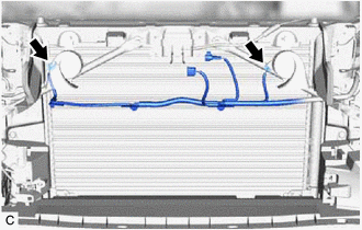
| (a) Disconnect the 2 horn connectors. | |
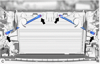
| (b) Remove the 2 bolts, 2 nuts and 2 upper radiator mounting brackets. |
|
15. REMOVE NO. 1 RADIATOR AIR GUIDE LH
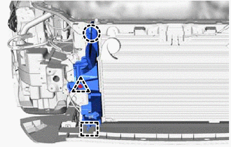
| (a) Remove the clip and disengage the claw. |
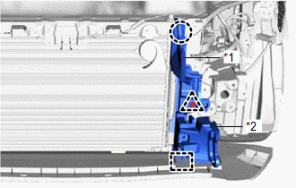 |
|
*1 | No. 1 Radiator Air Guide LH | |
*2 | Front Radiator Side Air Guide Plate LH | | |
(b) Disengage the guide to remove the No. 1 radiator air guide LH with the front radiator side air guide plate LH.
16. REMOVE NO. 1 RADIATOR AIR GUIDE RH
| (a) Remove the clip and disengage the claw. | |
(b) Disengage the guide to remove the No. 1 radiator air guide RH.
17. REMOVE UPPER RADIATOR SUPPORT SUB-ASSEMBLY
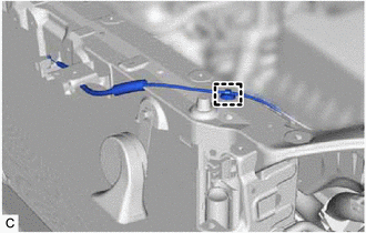
| (a) Disengage the clamp to disconnect the hood lock control cable assembly from the upper radiator support sub-assembly. |
|
| (b) Remove the 4 bolts and upper radiator support sub-assembly. |
|
18. DISCONNECT NO. 5 WATER BY-PASS HOSE
| (a) Disengage the 4 clamps to disconnect the No. 5 water by-pass hose and No. 6 water by-pass hose from the hose clamp (A). |
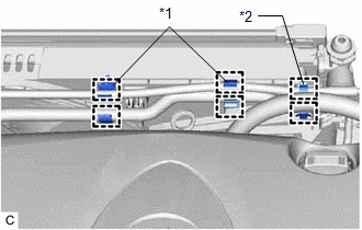 |
|
*1 | Hose Clamp (A) | |
*2 | Hose Clamp (B) | | |
(b) Disengage the 2 clamps to remove the hose clamp (B) from the No. 5 water by-pass hose and No. 6 water by-pass hose.
| (c) Slide the clip and disconnect the No. 5 water by-pass hose from the radiator assembly. |
|
19. DISCONNECT NO. 1 RADIATOR HOSE
| (a) Disengage the clamp and disconnect the No. 1 radiator hose from the fan with motor assembly. |
|
(b) Slide the clip and disconnect the No. 1 radiator hose from the radiator assembly.
20. DISCONNECT NO. 2 RADIATOR HOSE
| (a) Slide the clip and disconnect the No. 2 radiator hose from the radiator assembly. |
|
21. REMOVE RADIATOR ASSEMBLY
| (a) Disengage the 2 claws. | |
(b) Disengage the 2 guides to separate the cooler condenser assembly from the radiator assembly.
NOTICE:
Make sure not to damage the cooler condenser assembly when separating the cooler condenser assembly.
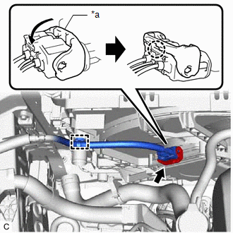
(c) Disconnect the cooling fan motor connector.
| (1) Disengage the claw and raise the lock lever to disconnect the cooling fan motor connector as shown in the illustration.
NOTICE: After
disconnecting the cooling fan motor connector, make sure that dirt,
water or other foreign matter does not contact the connecting parts of
the cooling fan motor connector. | |
(2) Disengage the wire harness clamp.
(d) Remove the radiator assembly with the fan with motor assembly from the vehicle body.
NOTICE:
Do
not apply excessive force to the cooler condenser assembly or pipe when
removing the radiator assembly with the fan with motor assembly.
| (e) Disengage the 2 claws. | |
(f) Disengage the 2 guides to remove the fan with motor assembly from the radiator assembly.
NOTICE:
Do not damage the radiator assembly when removing the fan with motor assembly.
22. REMOVE RADIATOR SUPPORT CUSHION
(a) Remove the 2 radiator support cushions from the radiator assembly.
23. REMOVE LOWER RADIATOR SUPPORT
(a) Remove the 2 lower radiator supports from the radiator assembly.






 for Initialization
 for Calibration


